
Additional updates on the construction of this kiln can be found at Kazegama Rebuild – 2016

Kiln Design
When designing a kiln, I start with the dimensions of the shelves that the wares are to be fired on. I then add a 2″ gap between the shelf edges and the back and side walls, 1″ for vertically placed 1″ thick Corelite kiln shelves that are the hot face of the walls, 4″ walls of fiber blanket or 4.5″ walls of K-23 soft bricks, and the metal frame.

Front of kiln with Corelite shelves against the front wall. Rear of kiln with no Corelite kiln shelves
To shield the walls of my Kazegama from chemical attack from wood ash or other soda sources, I mount a 1″ layer of Corelite kiln shelves against the kiln walls. There is an 18″ spacing between the edge of the front kiln shelves and the inside surface of the front wall where the blower burners blow flame and ash into the kiln. This 18″ spacing allows for the expansion and dispersion of combustion gases and wood ash as they enter the kiln.

The fiber blanket I use has a density of 8 lbs. per cubic foot. Using 4 inches of fiber blanket in the walls and lid allows for the trailer transport of my kazegama due to its light weight and flexibility. I use 1/4″ thick expanded metal for the lid and floor, and #9-3/4″expanded metal in the side walls. The 1/4″ thick expanded metal is much thicker than #9-3/4″ expanded metal and provides additional strength for the floor and suspended refractories in the lid.


The vertical corners and the lower edges of the metal frame are constructed with 2″ angle iron and the wall’s top edge and the lid are made with 2″ x 3″ angle iron. All fiber blanket for the walls, floor, and lid are placed into the metal frame in a “wall paper” fashion and held in place with 2″ handmade, porcelain buttons and 15 gauge nichrome wire. The fiber blanket walls and roof are covered with 1″ Corelite kiln shelves. These are held in place with 9 gauge-nichrome wire. The floor is covered with K-23 soft bricks, 1inch of fiber blanket, and 1″ kiln shelves. The #9-3/4″ expanded metal comes in 48″ widths that are sheared in half lengthwise. This set up gives the kiln wall a 24-inch height along with any additional height from the angle iron frame.


This kiln has been in use since 2001. It has gone through many improvements and a major rebuild in 2006 and 2116.
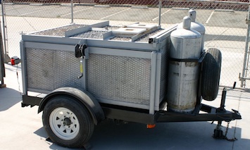
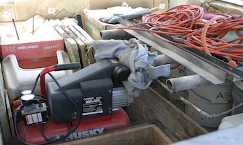
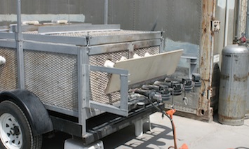
Here is the kiln in its current version with a shortened trailer. Most of the gear is stored inside the kiln for transport.
The kiln is bolted onto a trailer and used to have exterior storage spaces for all of the things needed for a firing. In 2008, I shortened the trailer by four feet and eliminated the storage areas. I now store the blower burner assembly, ash screens, bricks, shelves, tools, wood ash, and wadding, etc. inside the kiln. The lid is lowered and bolted into place for travel. Two – one hundred pound propane tanks and lid raising hardware are stored on the outside of the trailer in a secure manner. Trailers require a 60/40 weight distribution over the axel, with 60% of the traveling weight between the axel and the towing vehicle.
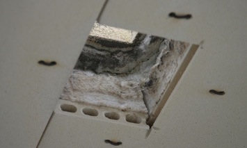
Notes on Fiber Blanket
One note about framing the kiln; steel exposed to heat needs to be at least 3/16 inch thick. The one-inch fiber seal between the lid and walls will compress after one or two firings, possibly exposing the frame to high temperatures. Keep in mind that heat exposure also exists in the areas around the burner ports, flues, and corners where the fiber layers should be overlapped. Fiber products that are commonly sold at ceramic supply stores are only rated to 2300’F. A refractory that is fired above its service temperature is going to shrink. Taking fiber blanket a hundred degrees over the service temperature, causes a 24 inch fiber blanket wall to shrink to 23 inches. I force a 24 inch panel of fiber into a 23 inch space to compensate for this shrinkage when designing the dimensions of the kiln walls and floor.
Lifting the Kiln Lid
Lifting the lid is achieved with a worm gear hand winch. There are two horizontal cross bars made of steel channel with square tubes welded on opposite ends that fit over the tops of two vertical masts made of 1-1/4” square tubes. These mast tubes drop into vertical square tubing on both sides of the kiln at the mid section of the kiln. A cable is run from the winch through 2 pulley wheels, up, across, and down to where it is attached to the lid support in the middle of the lid. A removable bolt is used to secure the cable loop to the lid support. The lid has 2 oversized square tubes that act as guides on the sides of the lid frame that capture and travel along the mast tubes as the lid is raised and lowered. The oversized square tubes keep the lid from binding against the vertical masts. The lid just floats on the cable as it is raised.

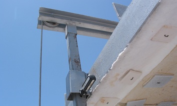
Any pitching of the lid can be counter balanced with bricks placed on the top of the lid. This is basically a guillotine set up and very dangerous. I drilled a hole in each mast where the lid comes to a rest. I insert screwdrivers or metal pins in these holes and then lower the lid frame onto them. This takes pressure off the cable and protects kiln loaders from a nasty headache.
Constructing the Burner System
The burner system is the heart of the Kazegama.
It is comprised of 4 blower burners welded to square metal tubing that forms the gas supply manifold. Each burner has its own ball valve for control of the propane gas and a Dayton #4C440 blower motor (new part # is 6FHX4) for the air supply. This 60 CFM blower motor has an air flap that opens and closes to adjust the air-fuel ratio. The blower is bolted to a steel pipe flange (2-1/4″ od x 1.5″ id), and that flange is welded to an 18-inch x 1.5″ black steel pipe.
Six inches from the pipe flange, a 1/4″ – socket weld – half coupling (Grainger part # 1MNY1) is welded onto the 18” pipe. There is a ¼ inch hole in the pipe where the half coupling is welded ( There is no insert or orifice). Another half coupling is welded to the gas manifold square tubing. Between the two half couplings is a ball valve, ¼” copper or aluminum tubing, and two male-threaded compression fittings. You can also just buy 1-1/2″ threaded pipe and a threaded flange for the 18″ section of the burner body instead of welding the steel pipe flange.

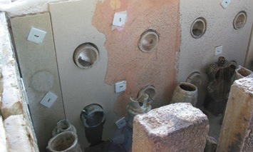
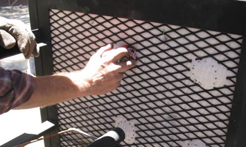
Installation of Burner Ports
To create holes for the burner ports, I place the burners into the mounting brackets and trace the burner tip positions onto the outside wall with a felt pen. I then remove the burners and cut out circles from the expanded metal where the burner ports are marked with dikes or a hand held grinder. The best tool for cutting clean holes in fiber products is a cheap hole saw. However, if the hole saw diameter does not match the diameter of the burner port tube, you can use the midsection of a soda can, and wrap it around the tube, and twist and push the tube through the fiber wall. Be sure to use leather gloves to protect your hands. I use extruded ceramic tubes in the burner ports because this reduces erosion in the burner ports wall caused by falling and melting ash. These extruded tubes are placed at least 1 inch into and outside of the kiln wall. Placing the tubes one inch into the kiln wall, keeps the ash off the inside wall where the ash can erode the surface. You can also purchase clay bonded silicon carbide tubes from Anderman Ceramics at 303-772-0975. Most importantly, always wear a facemask when working with fiber products.

Combustion Safety System
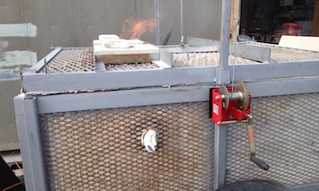
A trailer pilot is used as a safety system for this kiln. It works well for me, but is not as good as a solenoid safety system. A trailer pilot is positioned just under the tip of all 4 burners. It is connected to the gas manifold with a small gas cock that is adjustable. This is a 36″ long, 3/8″ stainless steel tube that is perforated down its length, and has a small air notch and orifice at one end. When there is a good yellow glow to the burner ports, the gas supply is turned off to the trailer pilot because the heat generated is enough to keep the burners ignited.


Trailer pilot, feed line, and gas cock on old set up. Original burner and safety set up from 1996.
With blower burners, it is quite easy to blow the flame right off the tip of the burner. If you don’t have an ignition source to combust the propane, you can have a serious explosion on your hands. You must always maintain an ignition source for any combustion system. These burners do not use flame retention nozzles because they would clog up with wood ash.

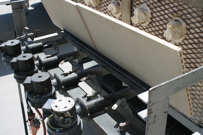
There is a tremendous amount of heat that comes from the burner ports, so I have welded an angle iron bracket onto the 4 burner tubes where Corelite kiln shelves are placed to create a heat shield. They do a great job of keeping the blower motors cool.

 copy")


")
")


