
(Little Wood-Fire Kiln)
When I was 17 years old, way back in 1974, my first introduction to ceramics were Shigaraki jars that were wood-fired and made with clays ladened with decomposed granite. My stepdad, Sueo Serisawa and my mother would bring back books and pots from their travels to Japan’s ancient kiln sites. The one book that I have to this day is Louise Cort’s “Shigaraki – Potter’s Valley”. It was a huge inspiration for me at the time as were pots brought home from Japan made by Takahashi Rakusai.


Ubaguchi-rimmed mizusashi called Sansei, with matching lid. Coiled and modeled. Ash glaze, possibly applied. Last decade of the sixteenth century.


Jar with rope pattern. The neck has a double rim. Shiny red-orange surface with olive-green glaze on lower front. Incense container in the shape of a roadside shrine. Hand modeled. Probably early seventeenth century. – from “SHIGARAKI – Potter’s Valley”

Takahashi Rakusai – Uzukumaru hanging vase and Shiho Handier (eared flower vase) brought back from my folk’s travels to Japan in the 1970s.
In 1996 I was in a gallery opening showing my pots with Sueo’s painting and ran into Kris Cox who had been a teacher of mine. He suggested that my work would lend itself to wood-firing. This led to a suggestion by my folks to befriend Greg Kennedy, a ceramics teacher at Idyllwild Arts where there was a wood-fire kiln. The kiln was built by Fred Olsen and his mentor Tomimoto Kenkichi. It was my first experience with the wood-fire process. Shortly after that, I developed the Kazegama as an alternative to wood-firing because I did not have a place where I could wood-fire on a regular basis.

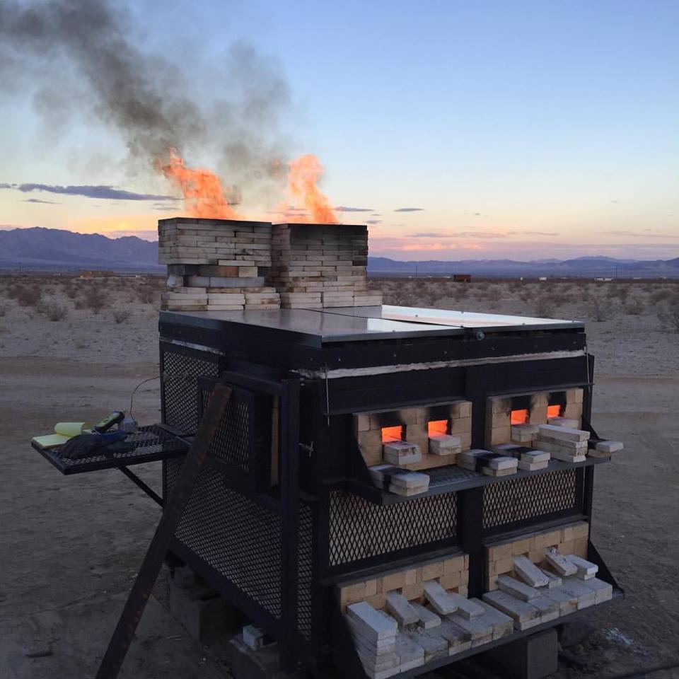
Then in 2001, I was involved in the creation the the Idyllwild Ceramic Survey in Idyllwild, California during the years 2001-2003. The ceramic conference was all about firing a variety of kiln types over the coarse of a week. I took this opportunity to design and build my first wood-fired kiln shown above, that has since been removed.
In 2003, I constructed another kiln shown below as the Akagama-Red Kiln. The concept for this kiln was to be one big firebox. So many kilns are built on successful models such as anagama and groundhog style kilns. But these kilns were originally built for efficiency and the capturing of heat to be used throughout the long length of the kiln. My approach was to build a shorter kiln with a three foot deep firebox and a five foot deep loading space. It was not designed for efficiency, but to get pots up close to the charcoal bed/firebox. This kiln was designed to be picked up by forklift and then transported to a permanent space. But this kiln sat in the yard of Aardvark Clay & Supplies where I work for many years. I finally found a home for the Akagama in 29 Palms and in the good hands of Jonathan Cross.
Komakigama Construction
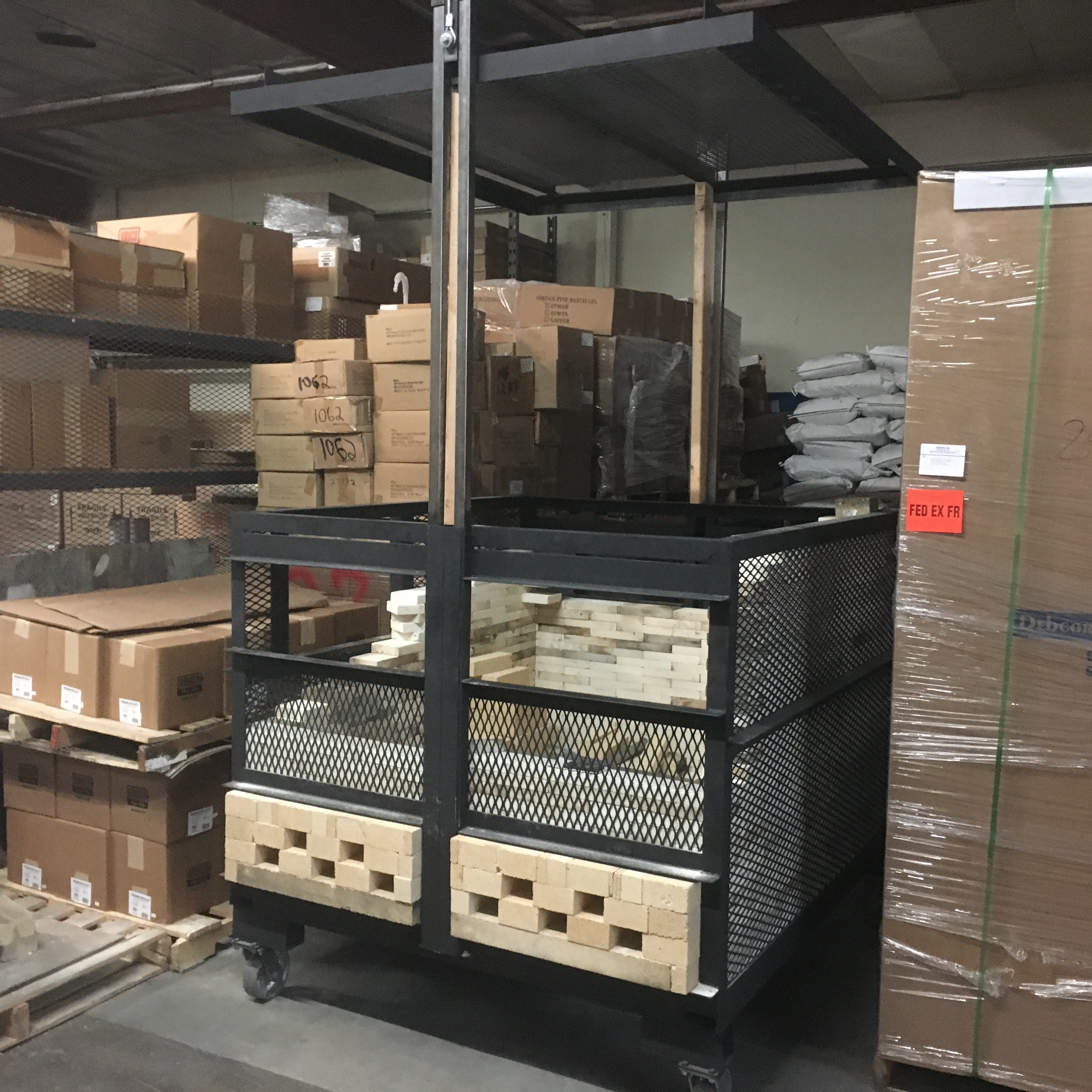
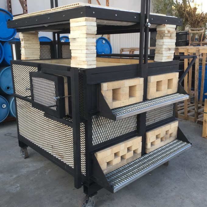
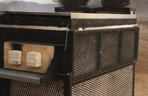
This kiln is very small which I like because it is much easier to control the application of heat, wood, atmosphere, and cooling and quicker turnover of firings and experimentation. I am also interested in pulling pots into the charcoal bed near the end of the firing.
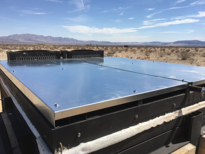
I like to construct kilns (even wood-fired kilns) using steel framing so that the kiln can be lifted and transported to any destination. When designing a kiln, I usually start with the kiln shelf footprint and design out from there to create the dimensions for the frame. This kiln was designed to be built and permanently mounted on my Kazegama trailer. So in this case, I started with the trailer frame and designed inward from there. For ease of construction, I mounted the kiln frame on dumpster wheels so I could move the kiln in and out of the warehouse as needed. The original design was to be a simple box with a very large coal bed area in the front and exit flues in the upper rear of the kiln. Ash was to travel up from the charcoal bed and be forced through the wares placed in the upper rear of the chamber as it exited through the rear flues. I decided later to add two small chimneys to control the flames leaving the kiln to protect the kiln frame. As it turned out, the kiln stalls out at around cone 4 without the draw from taller chimneys. Additional height has been added to the chimneys to get the kiln to fire off properly.
When I construct kilns, I document the process through photos so that I have a record of their construction and what I have done over my life related to clay. I also like to share what I have learned with others. Below is photo documentation of the Komakigama construction.
As the design progressed, it became a work in progress with lots of little tweaks being made over the almost 7 weeks of labor it took to construct the kiln.
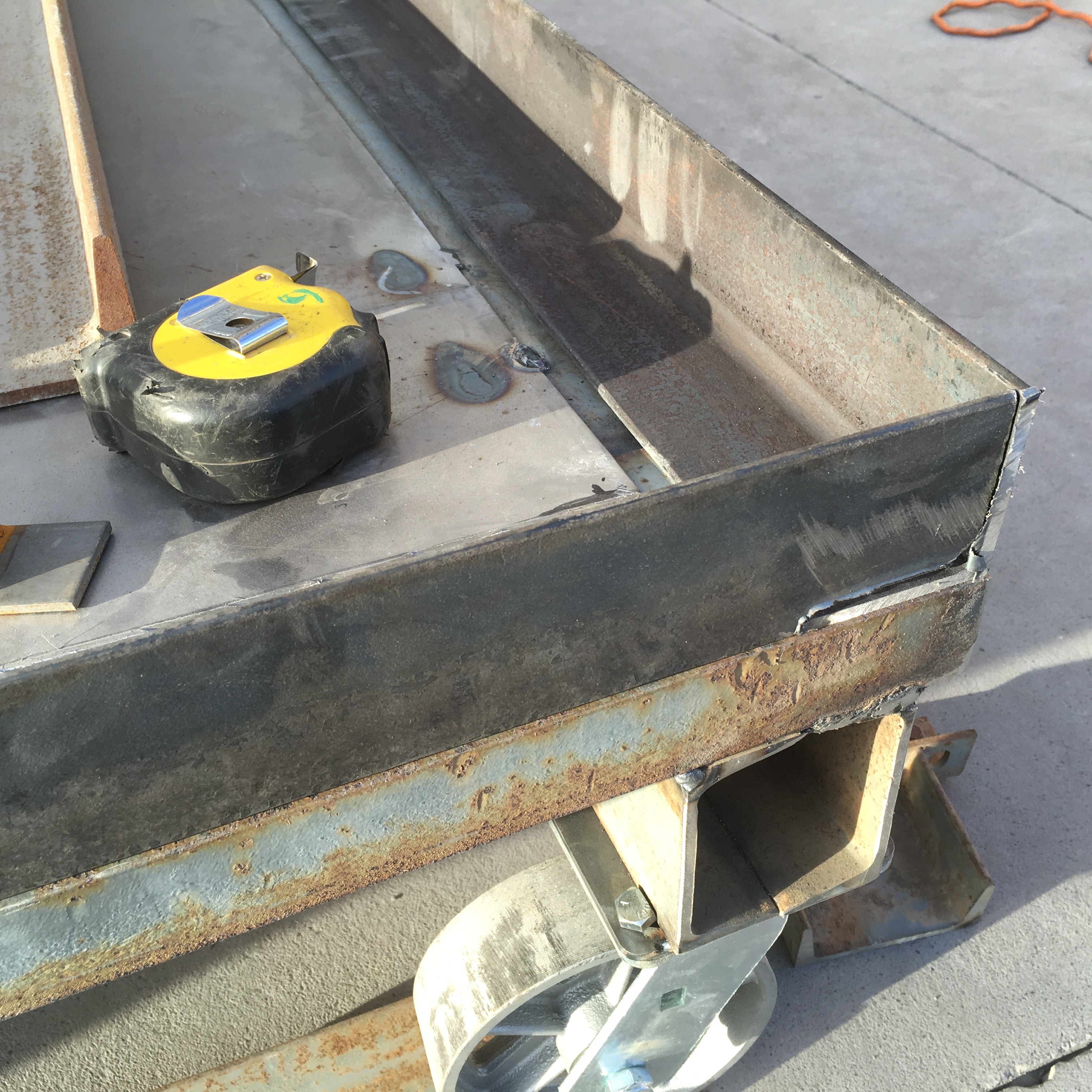

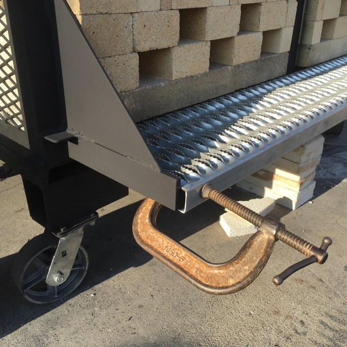
The base of the frame was formed with scrap 4″ x 1.5″ channel and 8 gauge sheet metal. The remainder of the frame is 2″ x 3/16″ angle iron. On the right is a shot of a tape measure, tube steel, and a C-clamp being used to square the wall of the frame. The length from the upper left corner to the lower right corner should match the length of the opposite length of the same wall. Once they are the same measurement, the square tubing is tightened against the angle iron frame to hold it steady as the corners are spot welded. All joints are spot welded and double check for being square throughout the frame before the final welds are made. This keeps the frame from going out of square due to the metal shrinking as it cools and pulling the frame out of alignment.


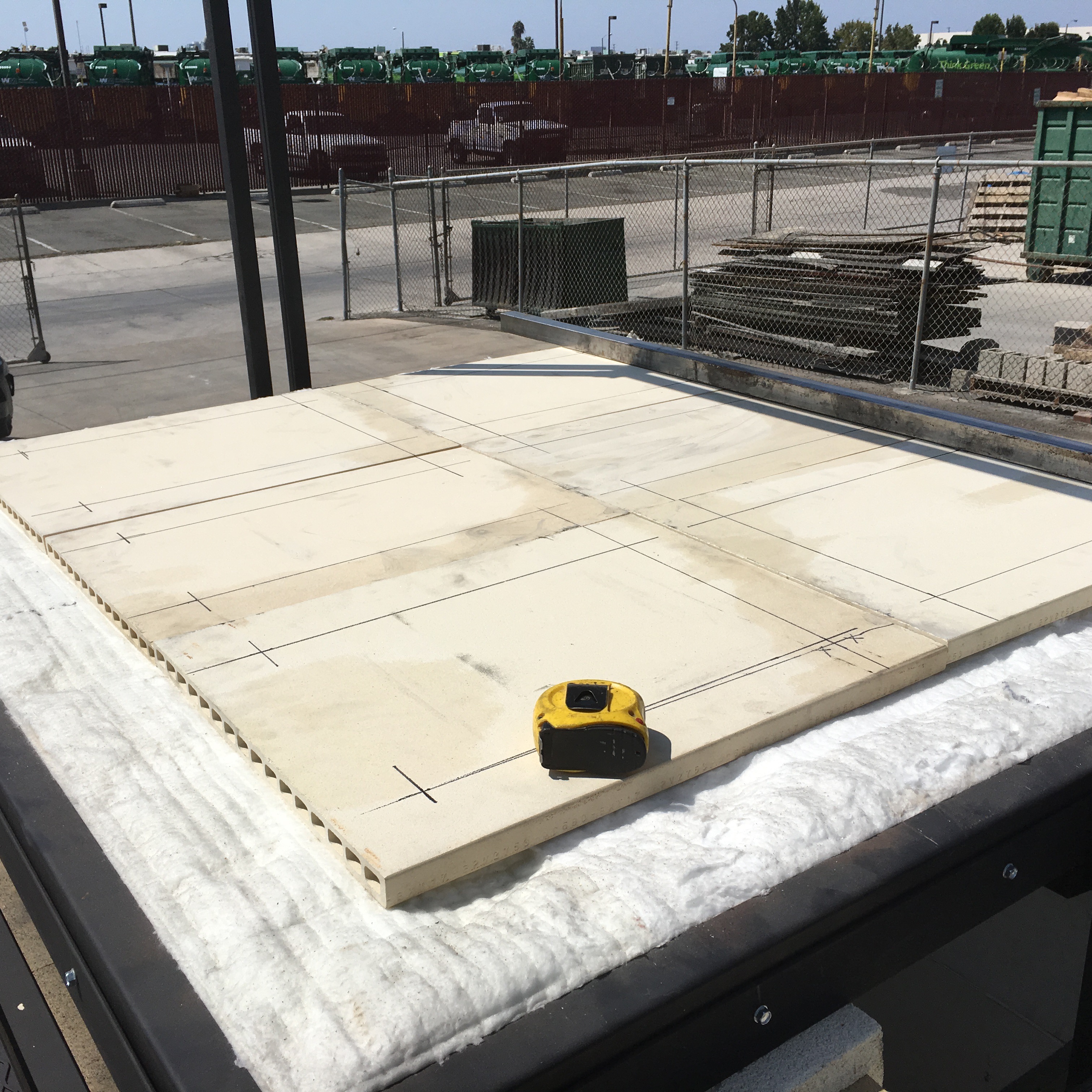
Bricks were laid out to set the locations of additional metal work.
Floor and Walls


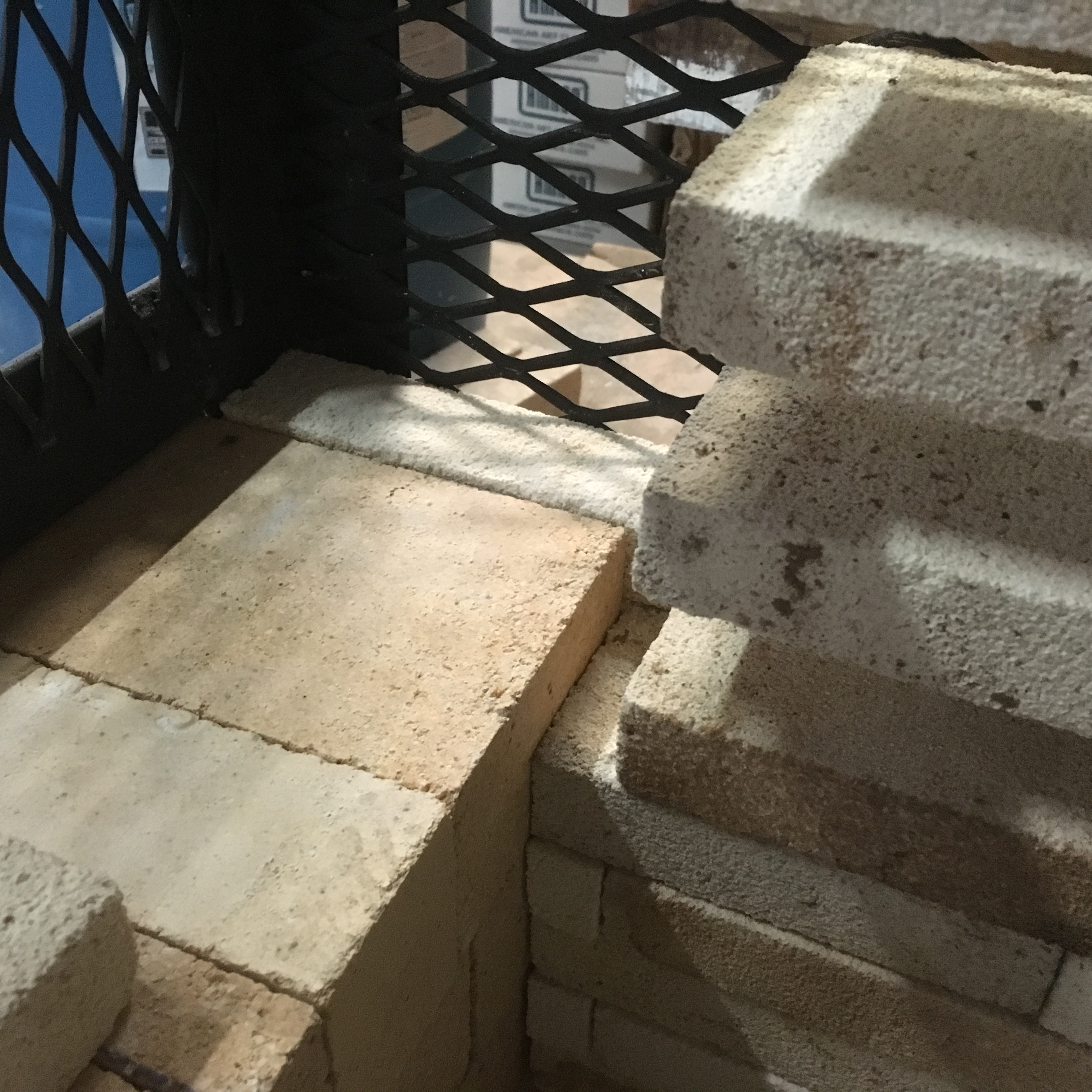
The bricks I used were 1.25″ soft brick splits (K-28) that I purchased from Ceramic Services for a very reasonable price, otherwise I would have used standard K-23 soft bricks. Helpers from left to right are Jamie Boran, James Mead, Mark Hendrickson, and Kaz Ota. I’m the guy in the cage… Fiber paper at 1/8″ thickness was used as a refractory barrier between the bricks and the sheet metal floor. The fiber is also used to help seal the kiln floor and walls for controlled reduction cooling by covering up any areas where oxygen could leak into the kiln.
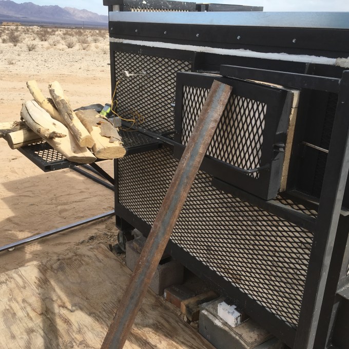
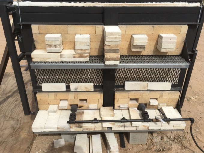
Wooden 2x4s are inserted under the lid for safety. The paint is a flat black engine enamel rated for 2000F. Standard hard bricks shapes were used where there was an opening for the stoke door, air ports or exit ports. The reason for this, is that the inside of these areas are exposed to erosion from ash, heat and abrasion.

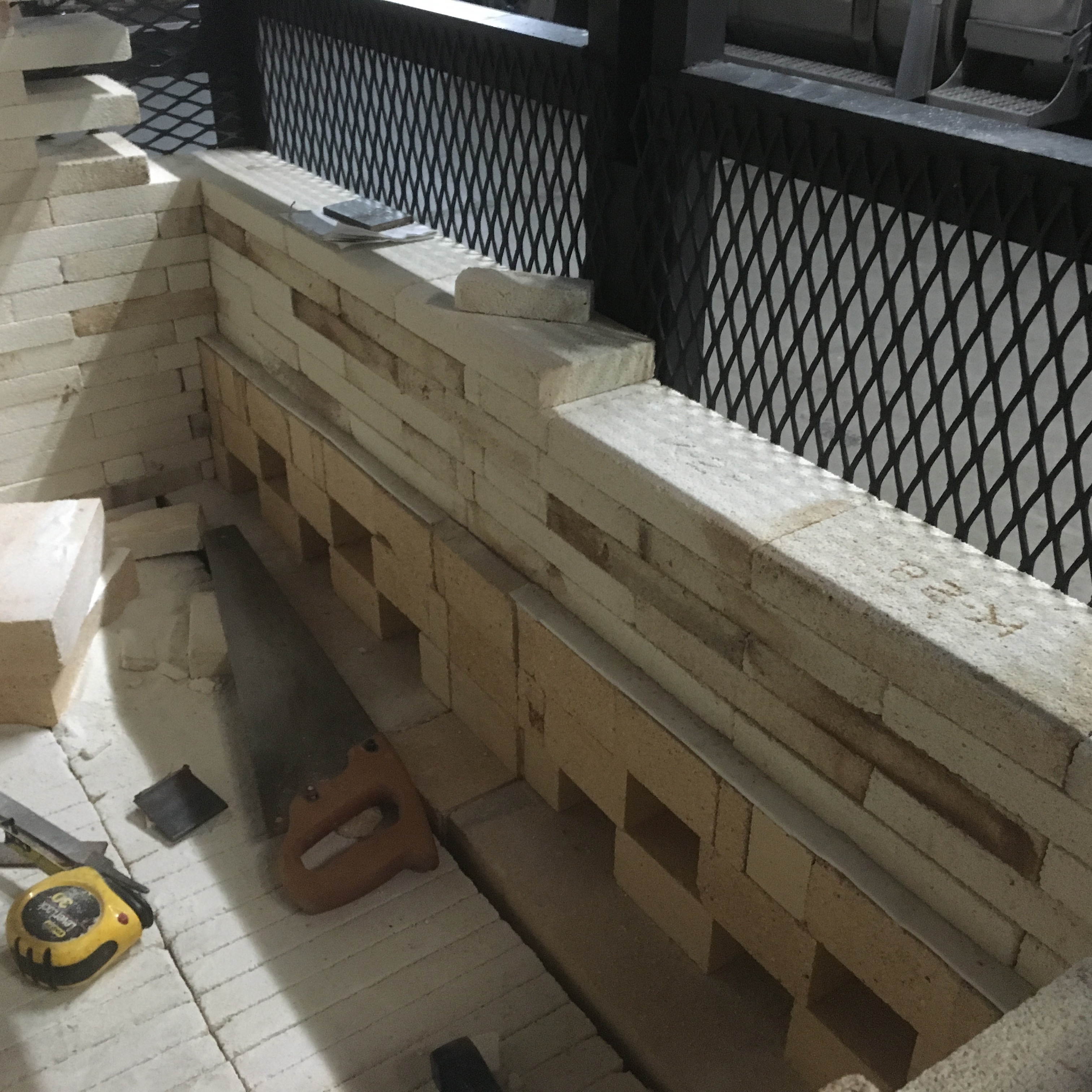


The upper inlet ports are for air to burn off un-combusted gases, pre-heating, viewing the work, and for accessing and pulling pots from the shelves and into the charcoal bed. The bottom ports are the primary air ports and are positioned to provide air under and over the grate made from kiln shelves.

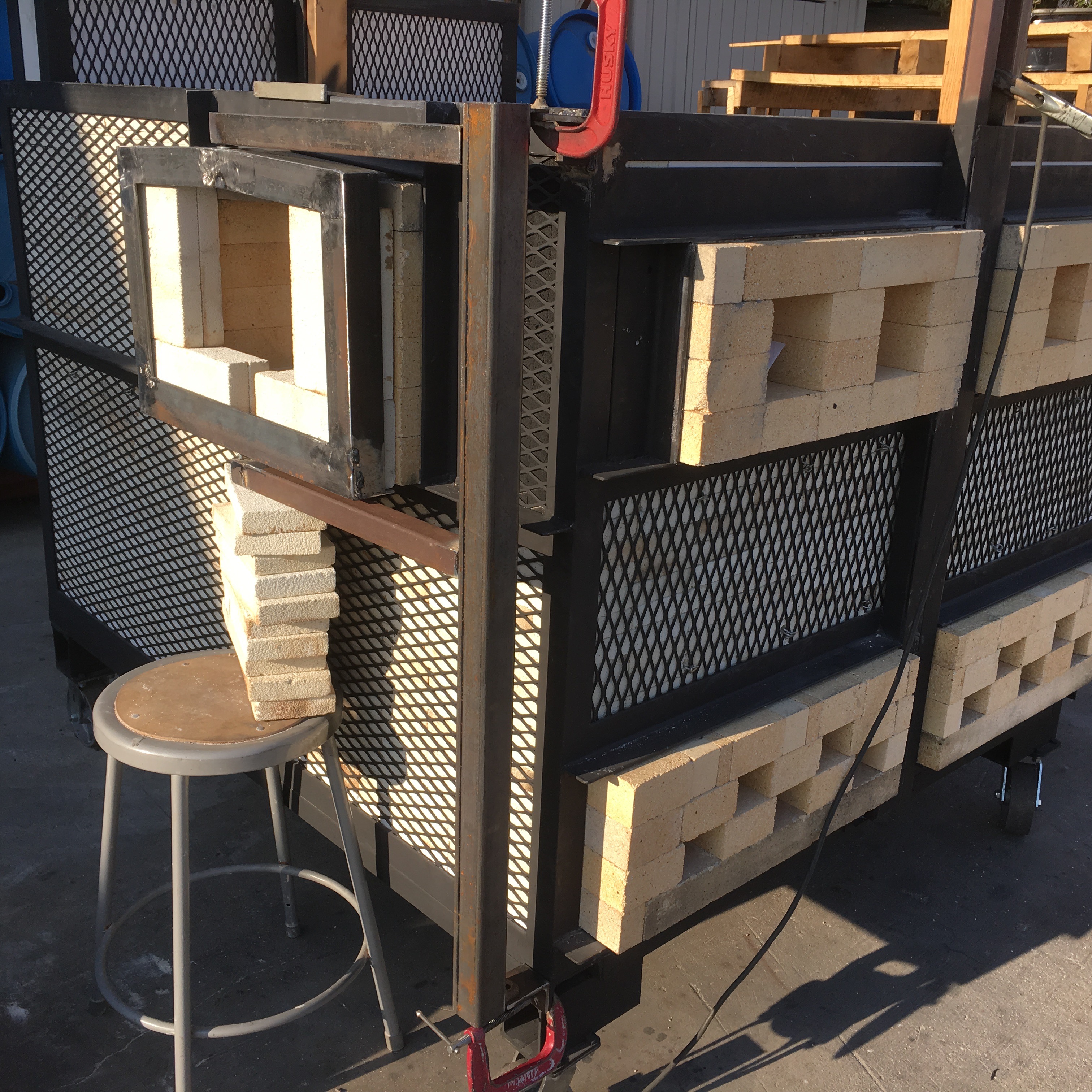
The stoke hole is made by cutting parallel angles into opposite ends of the hard brick shapes and then stacking the bricks to fall into themselves like a sprung arch. The bricks are supported on the outside edges with tapered wedges made of soft bricks that are braced against the wall bricks.

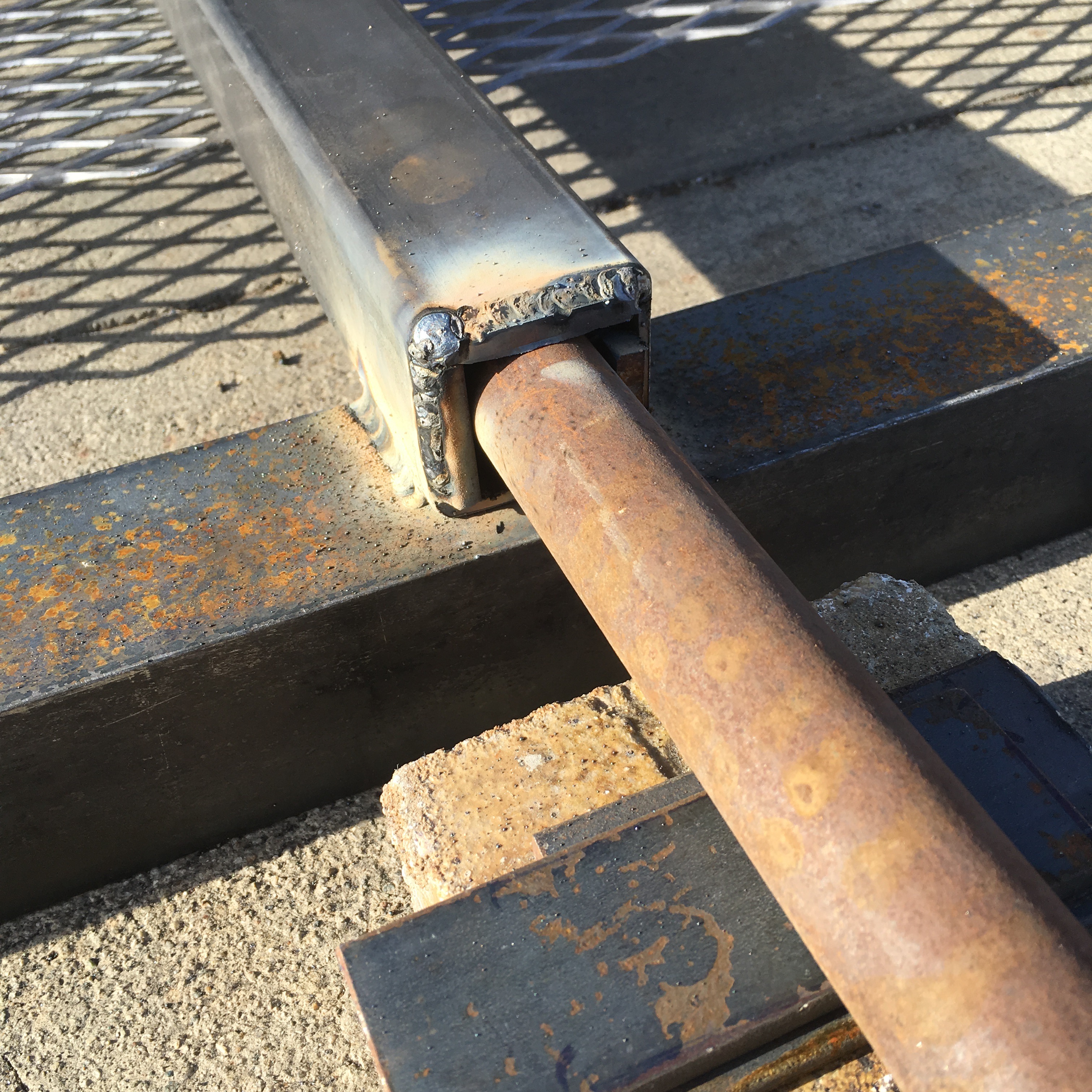
A 4-1/2″ hand-held grinder with a masonry cutting blade is used to cut a piece of angle iron to fit within the frame of the stoke hole and captures the top of the door bricks.

This is a very simple way to create a generous opening. The size of the opening is predicated on the size of the pieces of wood that will go through the opening.


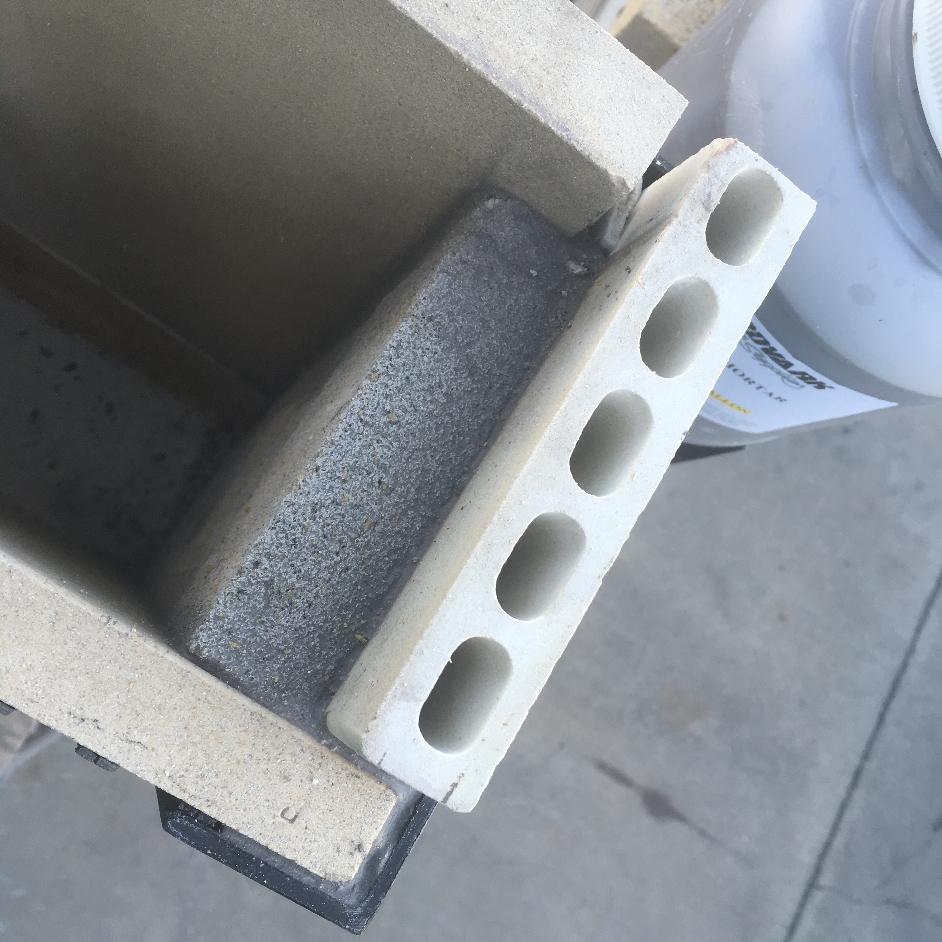
With input from Jonathan Cross, 1/8th inch ceramic fiber paper was inlaid into the walls to form an air-tight seal. The reason for this is to stop air from entering the chamber which can inhibit the reduction cooling process and atmosphere. Where ever there were soft bricks, fiber paper was applied as well as a layer of Corelite kiln shelves for the hot face. This protects the soft bricks from erosion by heat and ash.

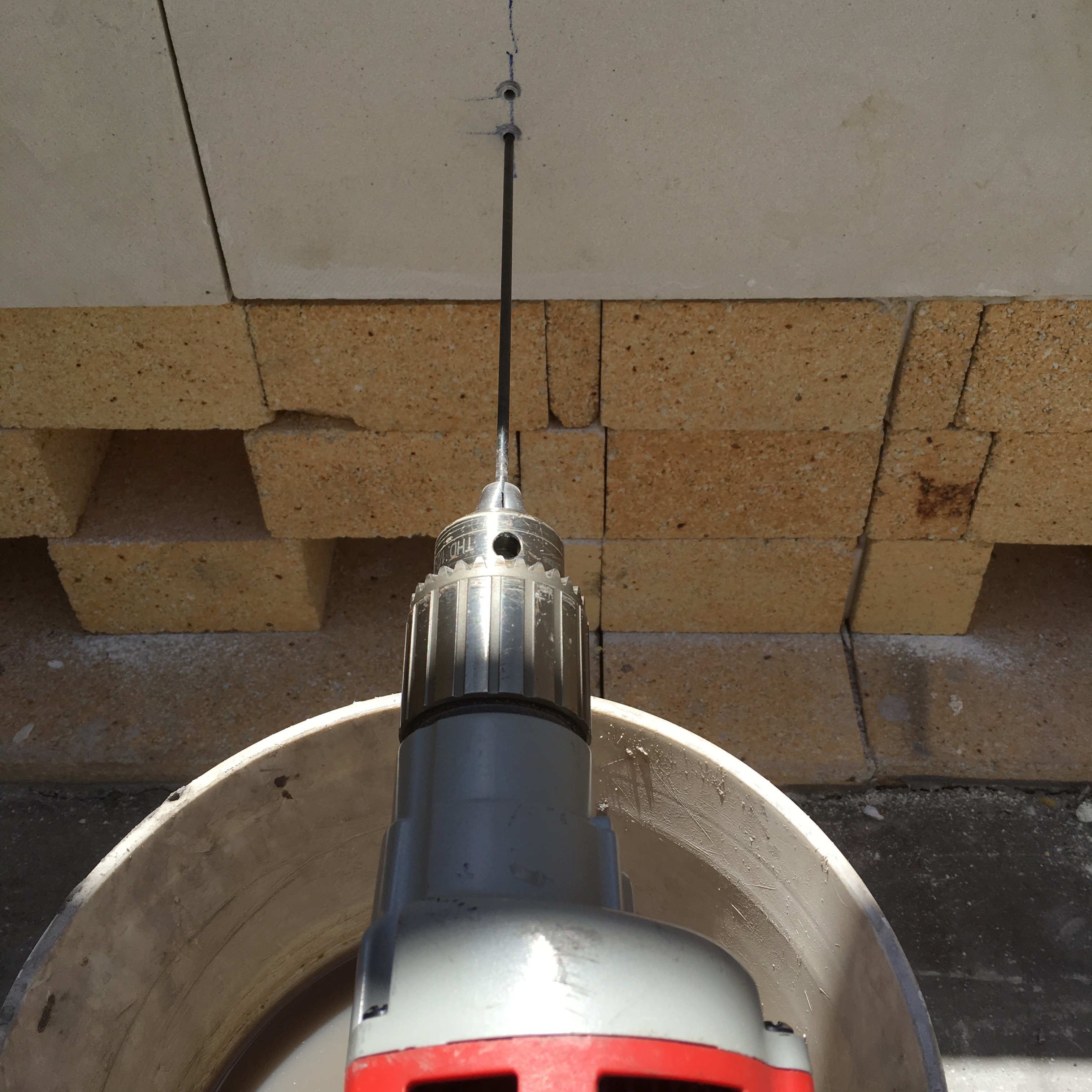
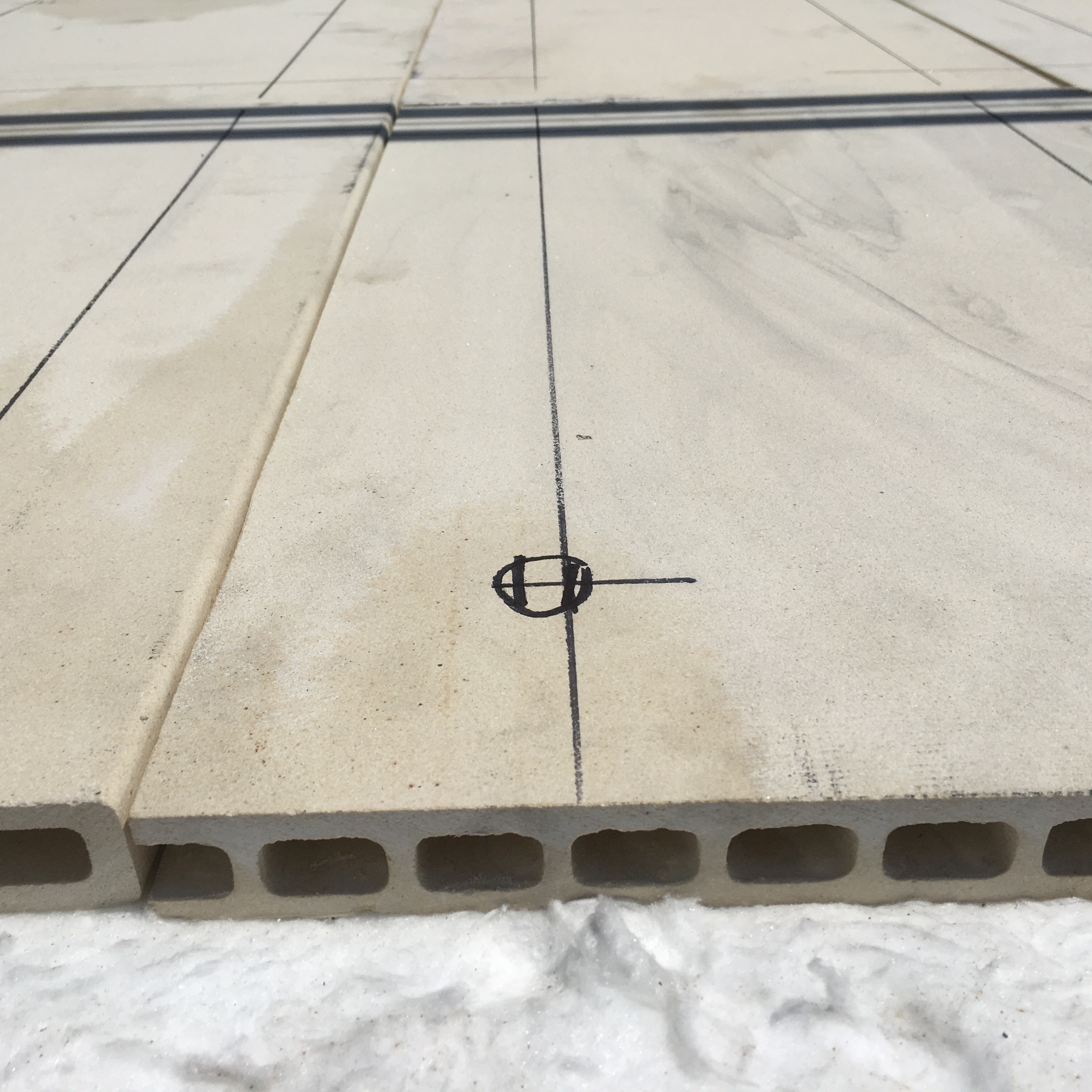
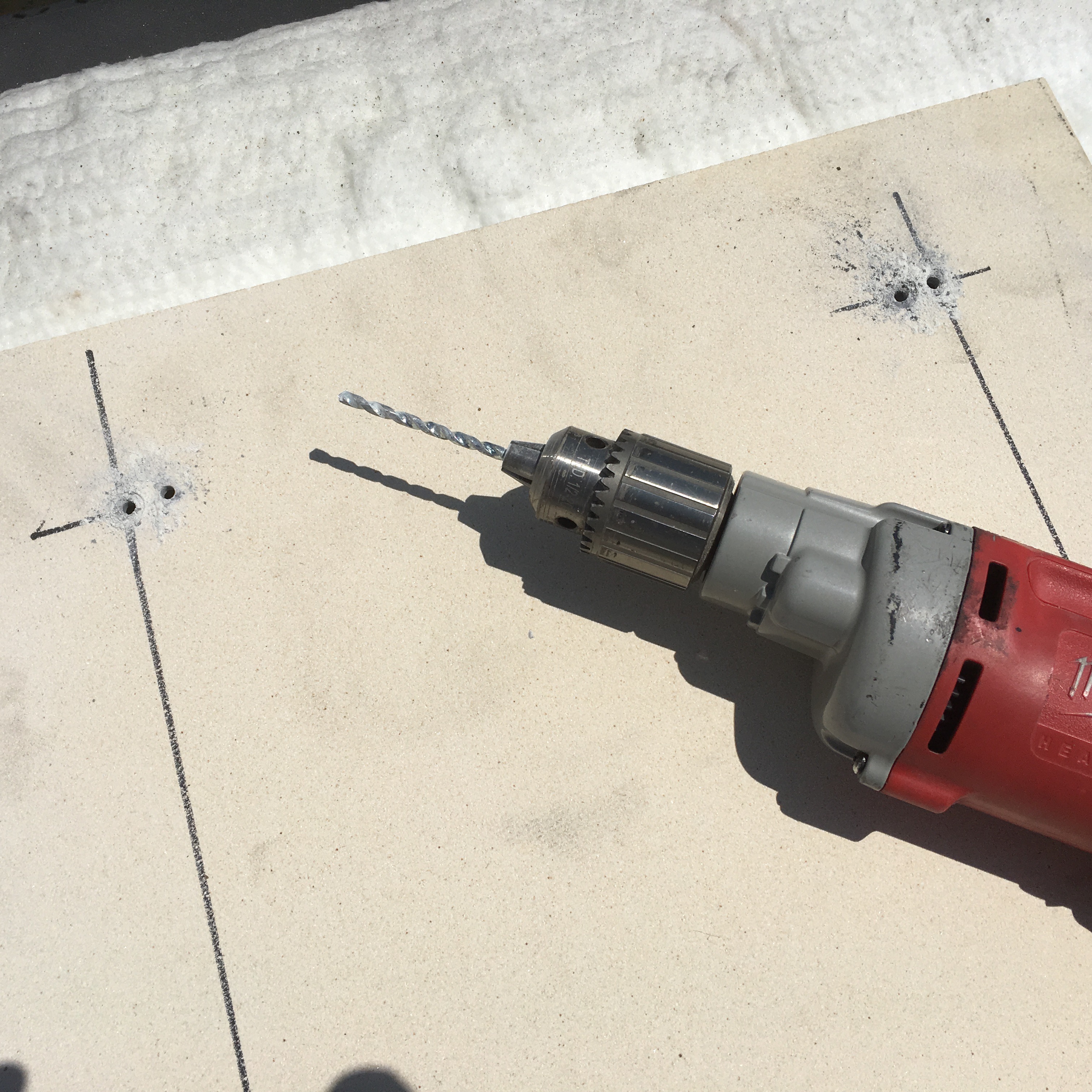
To anchor the Corelite kiln shelves to the wall, I measure the location of where nichrome wire anchors should probably go, and then double check on the outside of the kiln to make sure there is no framing or other obstructions. I then use an 1/8th inch masonry drill bit to drill through the Corelite kiln shelf and a 12 inch long standard metal drill bit for drilling through the soft brick wall.


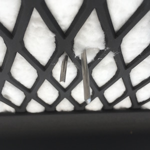
8 gauge nichrome wire is used to hold the shelves in place against the layer of ceramic fiber paper and the soft brick splits. The wire is bent around needle nose pliers to form a long U shape and inserted into two holes and pushed through the holes to the outside of the wall. The two wires should end up on either side of a section of 3/4 – 9 gauge expanded metal where it is twisted and the tips are bent over so that human flesh is not snagged.

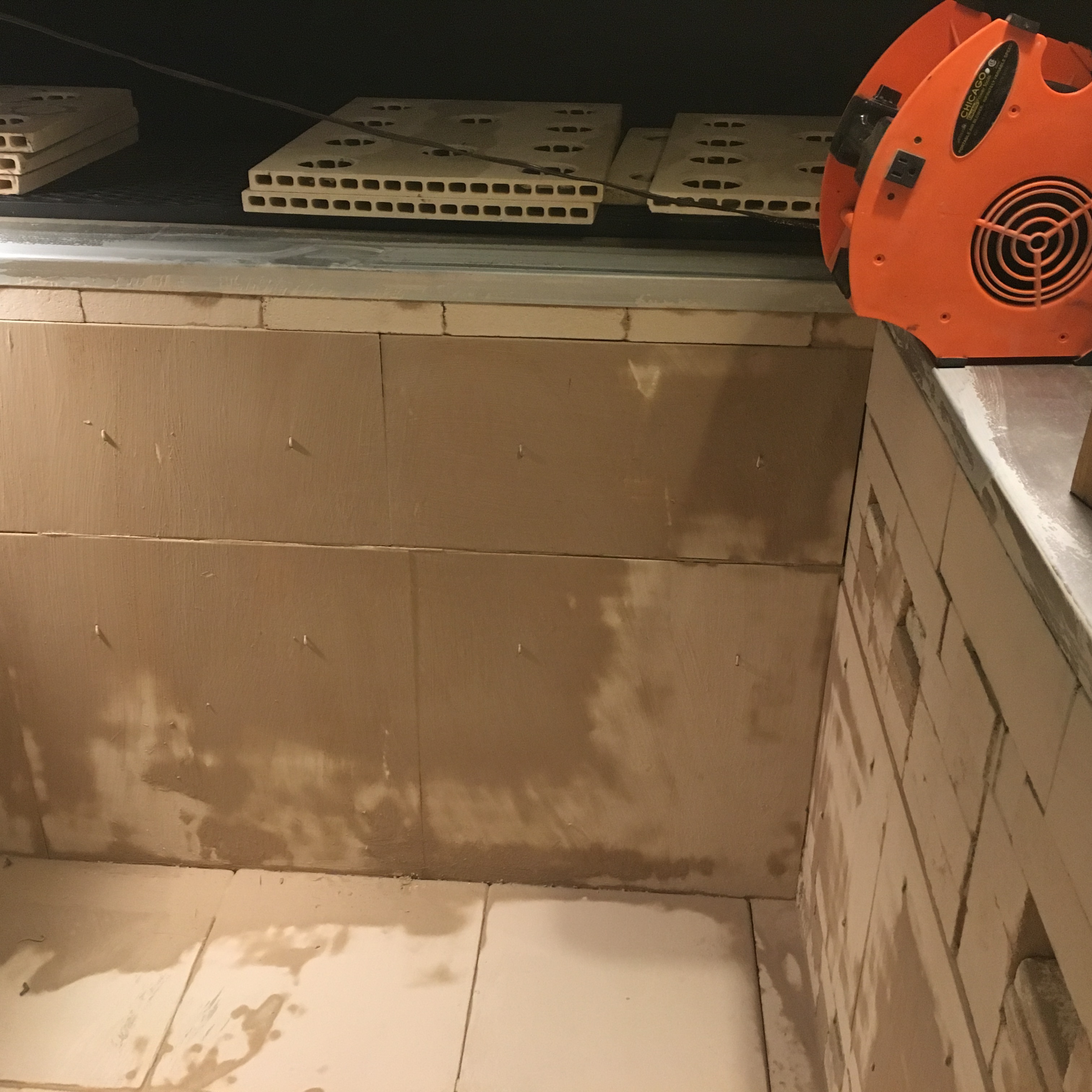
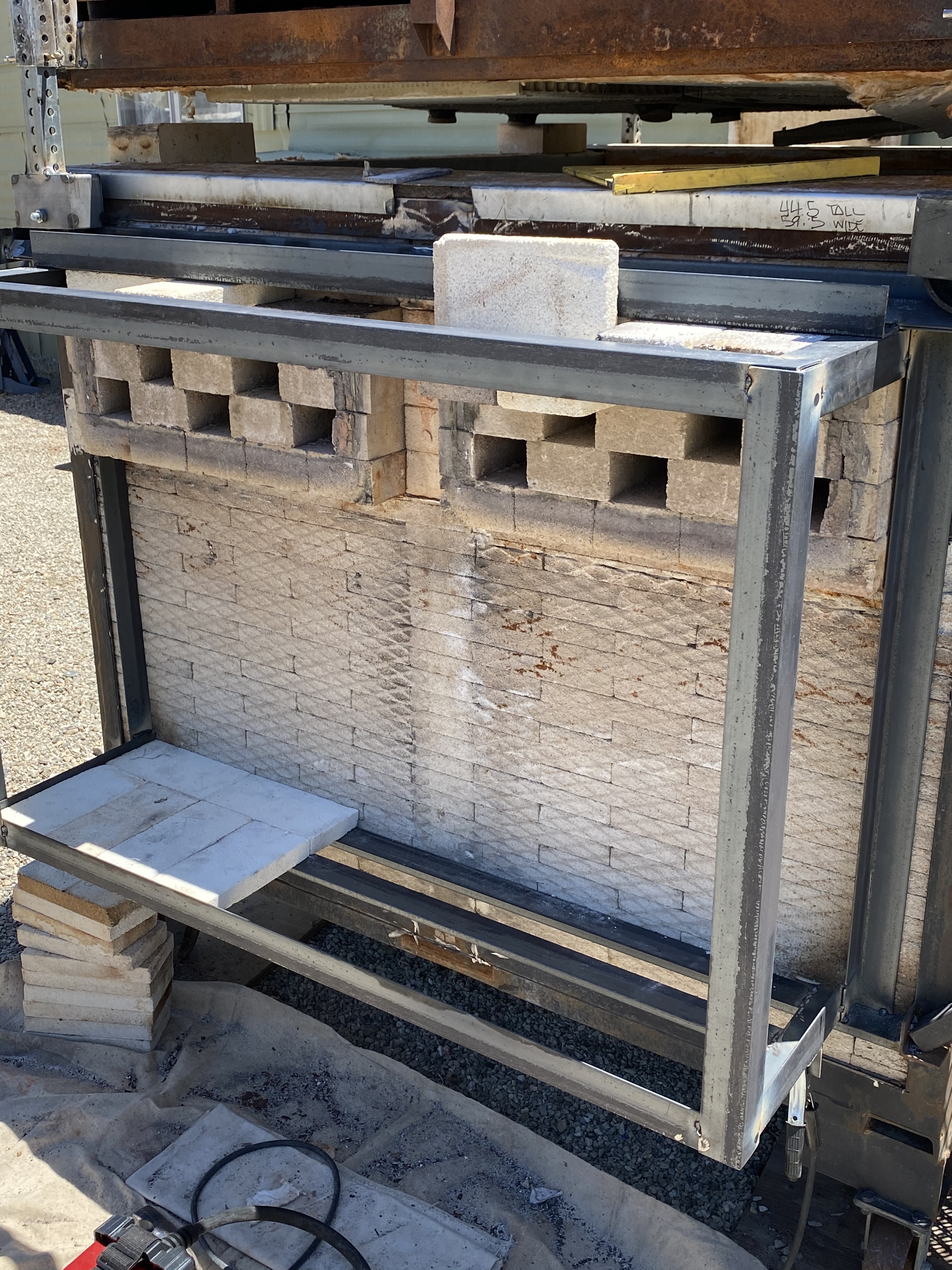
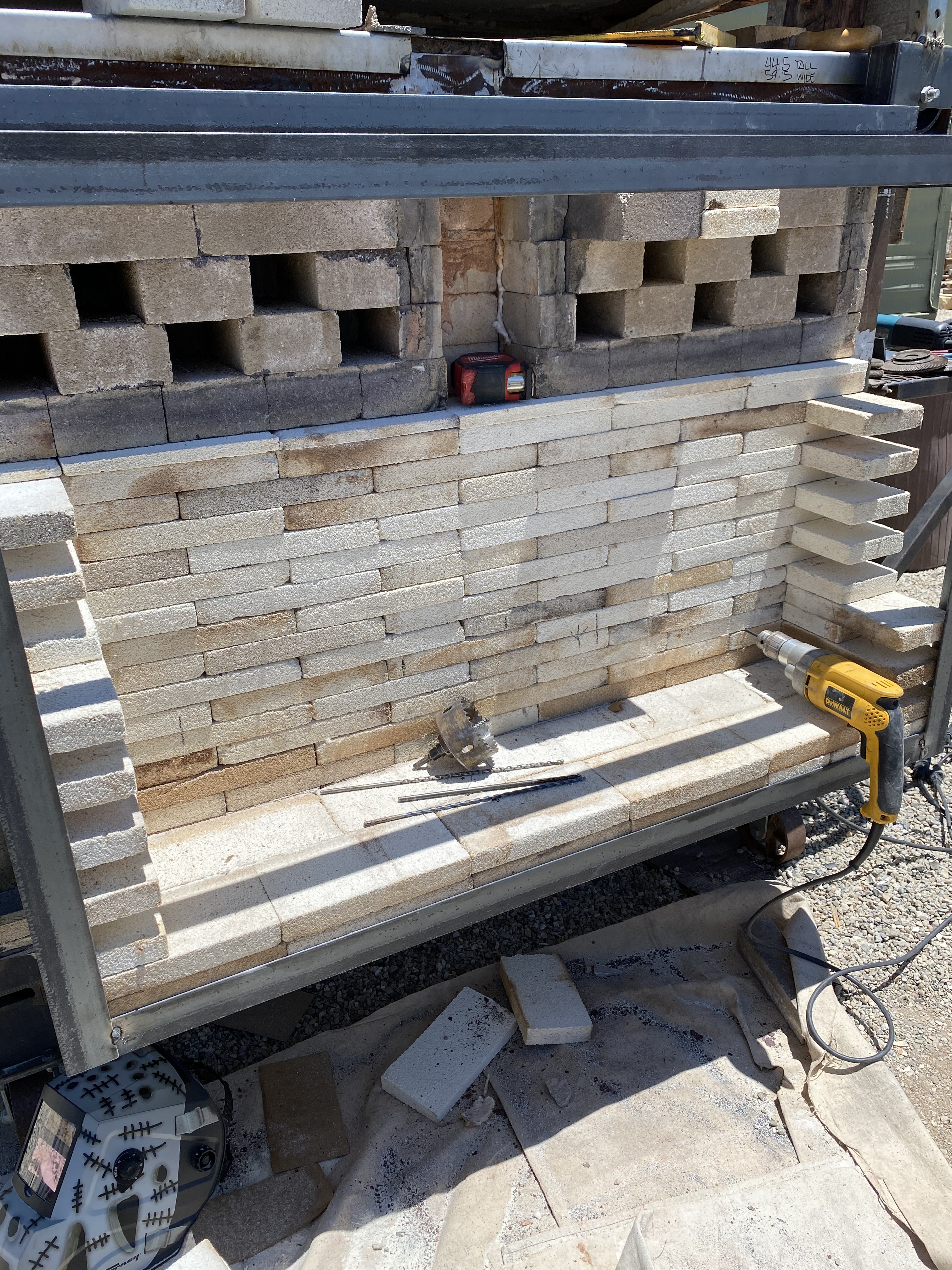
Here is the layout with a hot face of Corelite kiln shelves and hard bricks. The shelves cover a layer of ceramic fiber paper and soft bricks. Fiber paper is used as expansion joints.

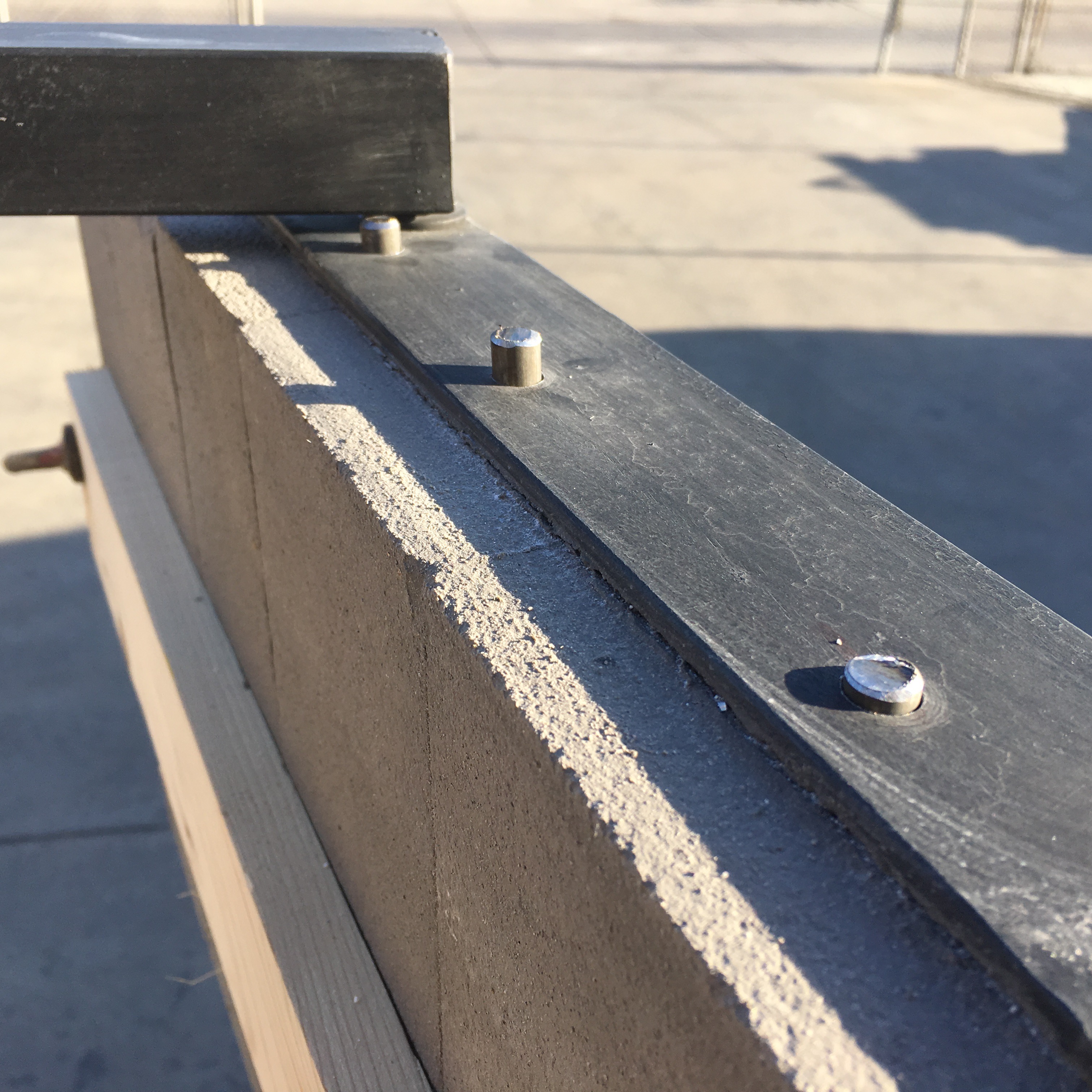
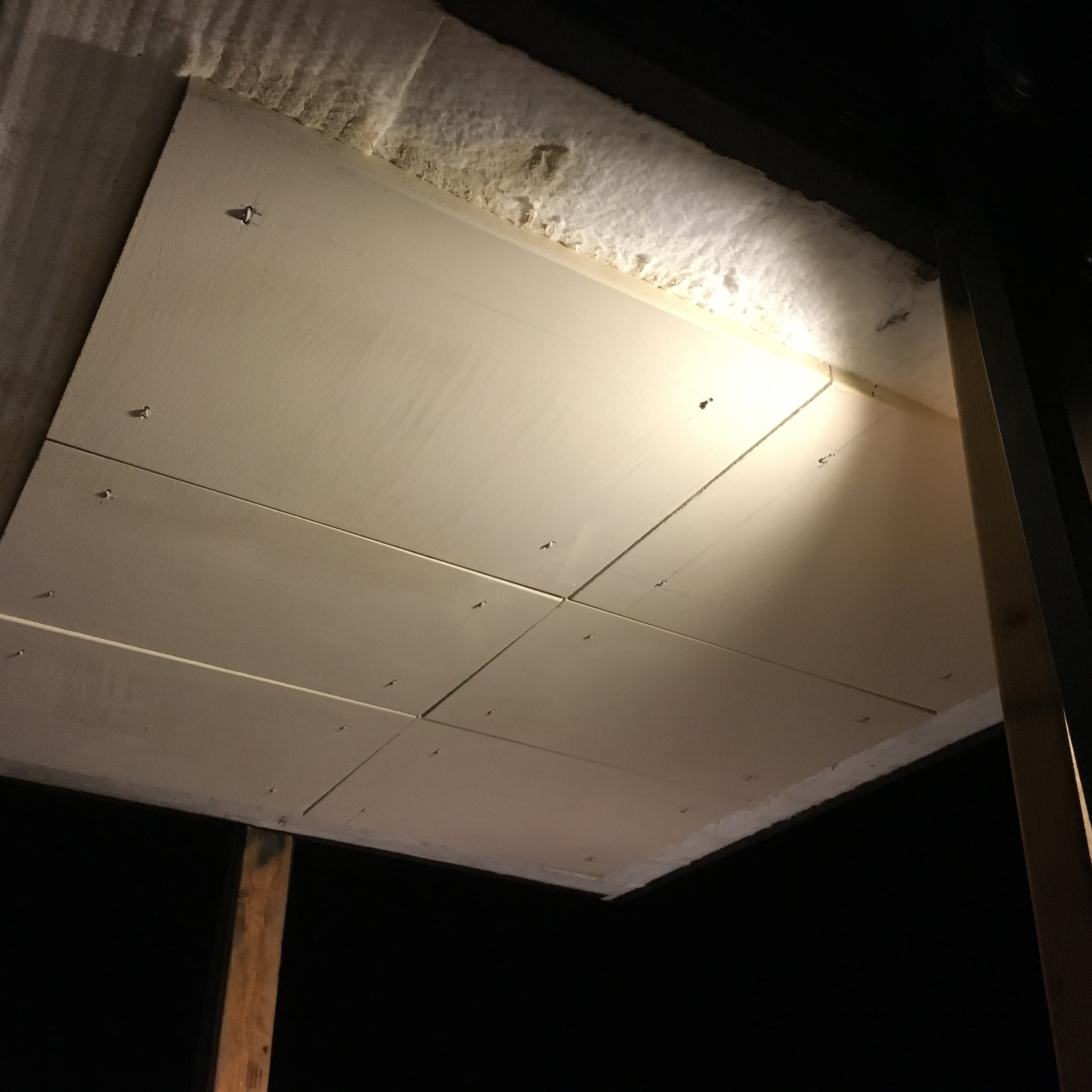
Hard bricks are placed all around the top perimeter of the kiln just under the angle iron frame where a 1 inch layer of fiber blanket will form a seal with the lid.
Chimney Construction


The frame of the left chimney floor was squared and spot welded. Then the other chimney frame was squared and spot welded. Then both floor frames were lined up with long pieces of tube steel, C-clamps and a carpenters square.

Then the remainder of the chimney frames were squared, spot welded and the final welds completed.


1/8th inch ceramic fiber blanket was inserted between the hard bricks to form expansion joints. Ceramic fiber paper was also used to seal the corners between the hard brick shapes and the soft brick walls. It was also employed as a way to adjust the height of the bricks where they cross over the angle iron to protect the angle iron from heat and to adjust the height of the hard bricks where they crossed over the frame.

Fiber paper was placed in the floor to shield the metal work. Corelite kiln shelves were used to form the lining of the chimneys. This has become a design flaw, as the heat that comes through this Corelite layer is quite hot and generates red heat in the metal frame between the lid and the chimney frames. This issue is being resolved at a later date with the addition of a layer of soft brick splits on the inside of the chimney walls.


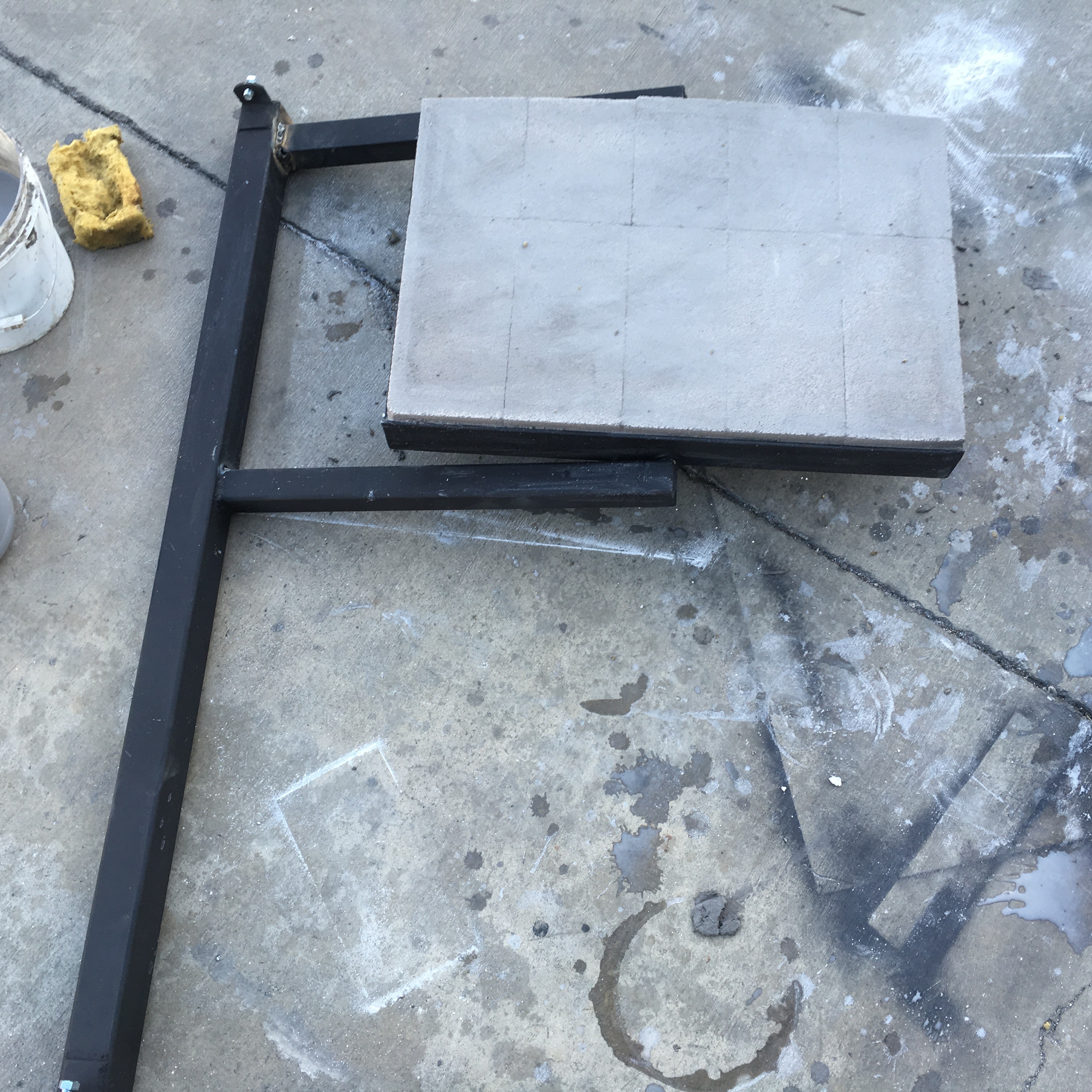
A lip of angle iron was added at the rear/top of the chimney to create a surface to rest the dampers on. The surface was created by cutting two mirror image pieces of Corelite kiln shelves and mortaring them into the angle iron frame. The dampers fill the entire width of the chimney and are the depth from the opening of the flue opening to the angle iron frame. This way, when the damper is pulled out to the angle iron frame, I know the flue is wide open.

This is a temporary fix for the chimney. The original chimney was not tall enough and the kiln stalled at cone 4. So at this time we are using the addition of bricks shown here which works very well as a temporary fix.
Lid Construction


The frame of the lid was designed to support a 4′ wide sheet of expanded metal which is used for anchoring fiber blanket and Corelite kiln shelves with 9 gauge nichrome wire.

A piece of pipe is welded within the lid frame which will allow the lid to rotate on the pipe that rides on cables. The pipe travels all the way to the other side of the lid.

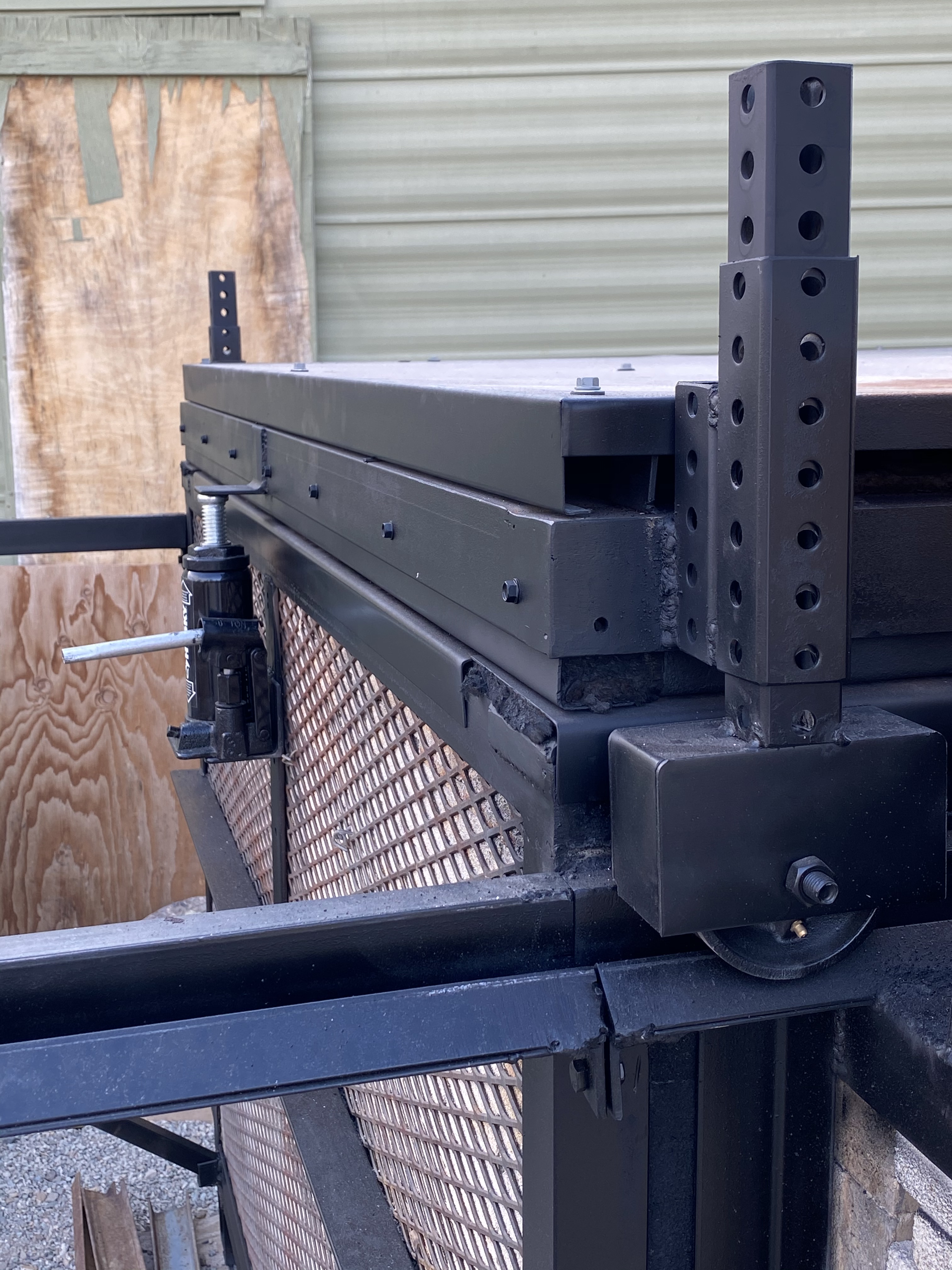
Four square tubes (vertical masts) are inserted into vertical tubes of a larger dimension that are welded to the kiln frame. Then a horizontal assembly of 2″ inch channel is fabricated to fit over the four vertical tubes. This forms the lid lifting assembly.


Lifting cables are attached to the pipe ends and wrapped around the pulley wheels at the top of the lifting assembly.


The pic on the left shows the cable wrapped around the pipe. This is true for the other side of the lid. The lid has a square tube retainer that has a hole in it to receive the pipe. This is placed between the two vertical “masts”. This retainer holds the lid in a horizontal position as it travels up and down. When the retainer is removed, the lid can be rotated for servicing without the need for a forklift. The pipe will rotate within the cable loop. The pic on the right shows the two cables that have come from the lid and traveled up and over the pulley wheels and down over the side of the lid lifting assembly. The cables are being held under tension by a water bottle to find the location of the crimped loop where a winch cable will be connected. The lid was clamped to the kiln frame and then the cable was put under tension to set the location of the loop. The location of the pulley wheels are important. They had to be located in a location that allowed the cable to travel freely to the winch and the pipes.


This is the horizontal assembly that has two square tubes on both ends. These tubes are placed over the mast tubes and this entire assembly in combination with the winch and cables lifts the lid.

With the two cables connected to the lid, the pulley wheel locations are noted. Then holes are drilled in the middle of the channels. Once the pulley wheels are mounted, the two cables are pulled tight at the wire rope sleeve and thimble loop shown above the water bottle. Once this is done and the two cables have the same tension, the wire rope sleeve is crimped tight. A cable with a threaded quick link rated to 1800 lbs. will be attached to this loop and the winch.
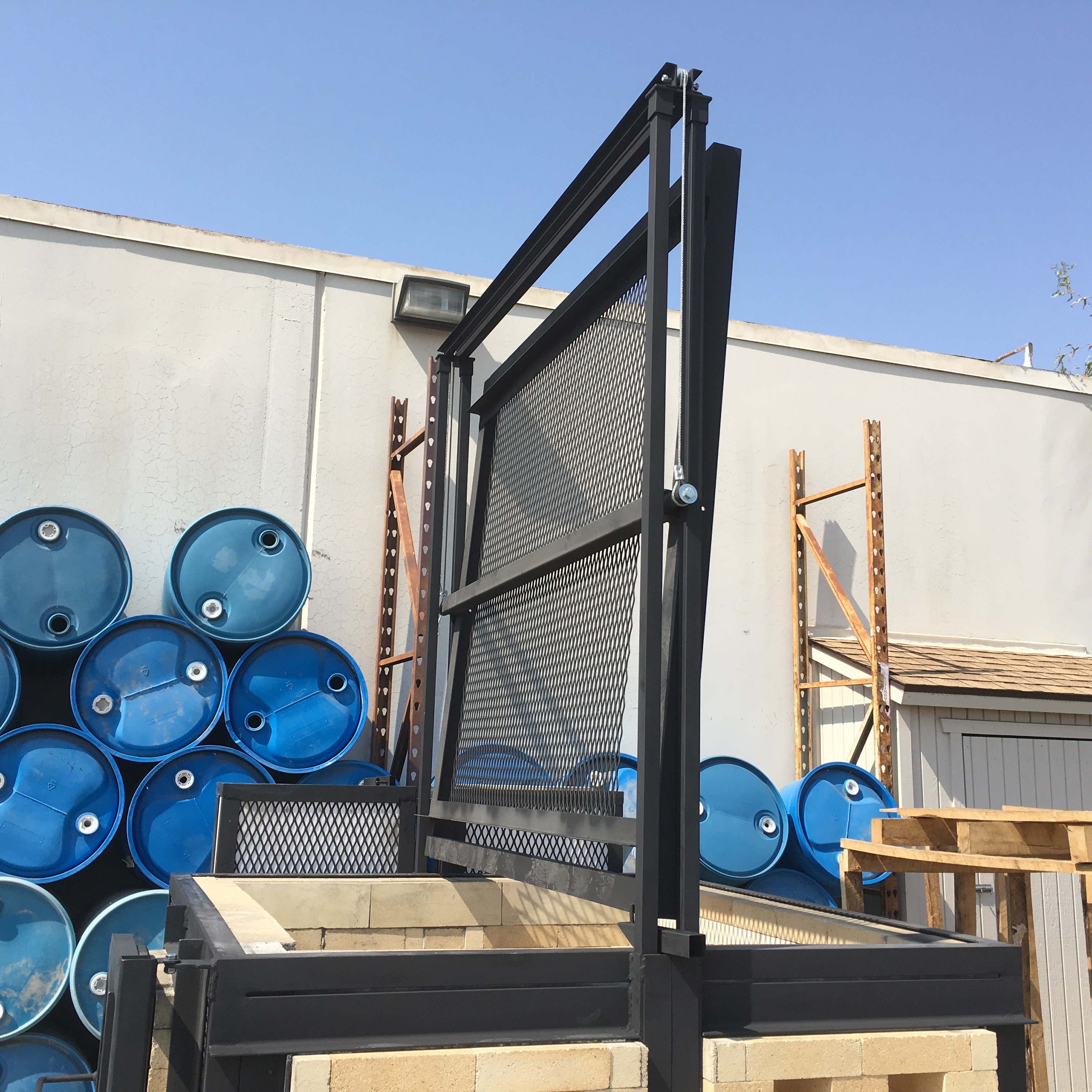
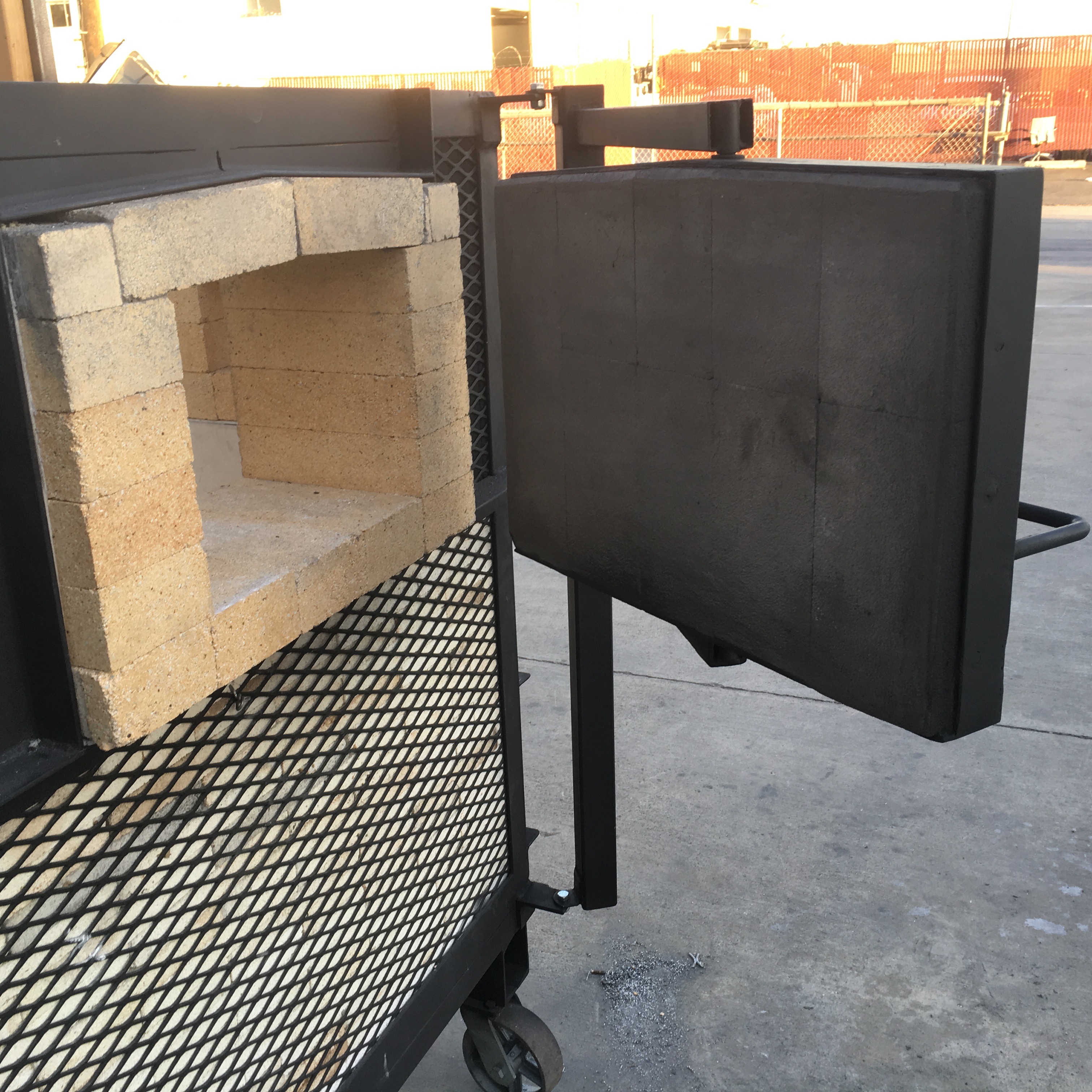
Here is the intent of the design. It allows the lid to be flipped over for installation and repairs of refractories.
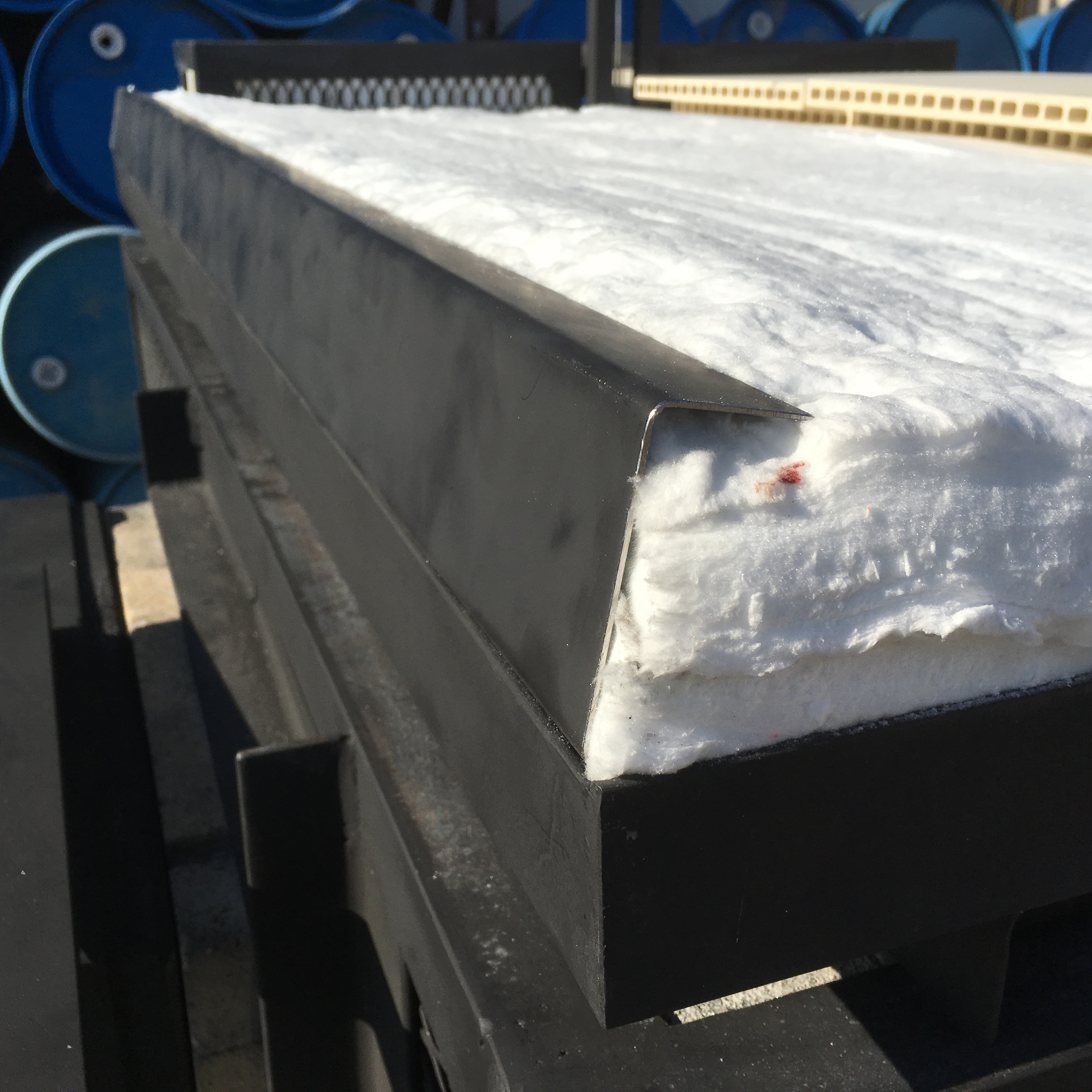
The lid is made of 4 inches of 8 lb. density fiber blanket which is compressed into a piece of folded sheet metal channel. The fiber comes in 24 inch wide rolls. The fiber is laid down in 4 – 1 inch layers and the seams are overlapped.

C-clamps are employed to hold the channel parallel with the frame and hold it steady for the insertion of self-tapping screws that hold the components together.

The lid is lowered upside down onto bricks so I can enter the kiln and twist the ends of the nichrome wire hangers in the lid.
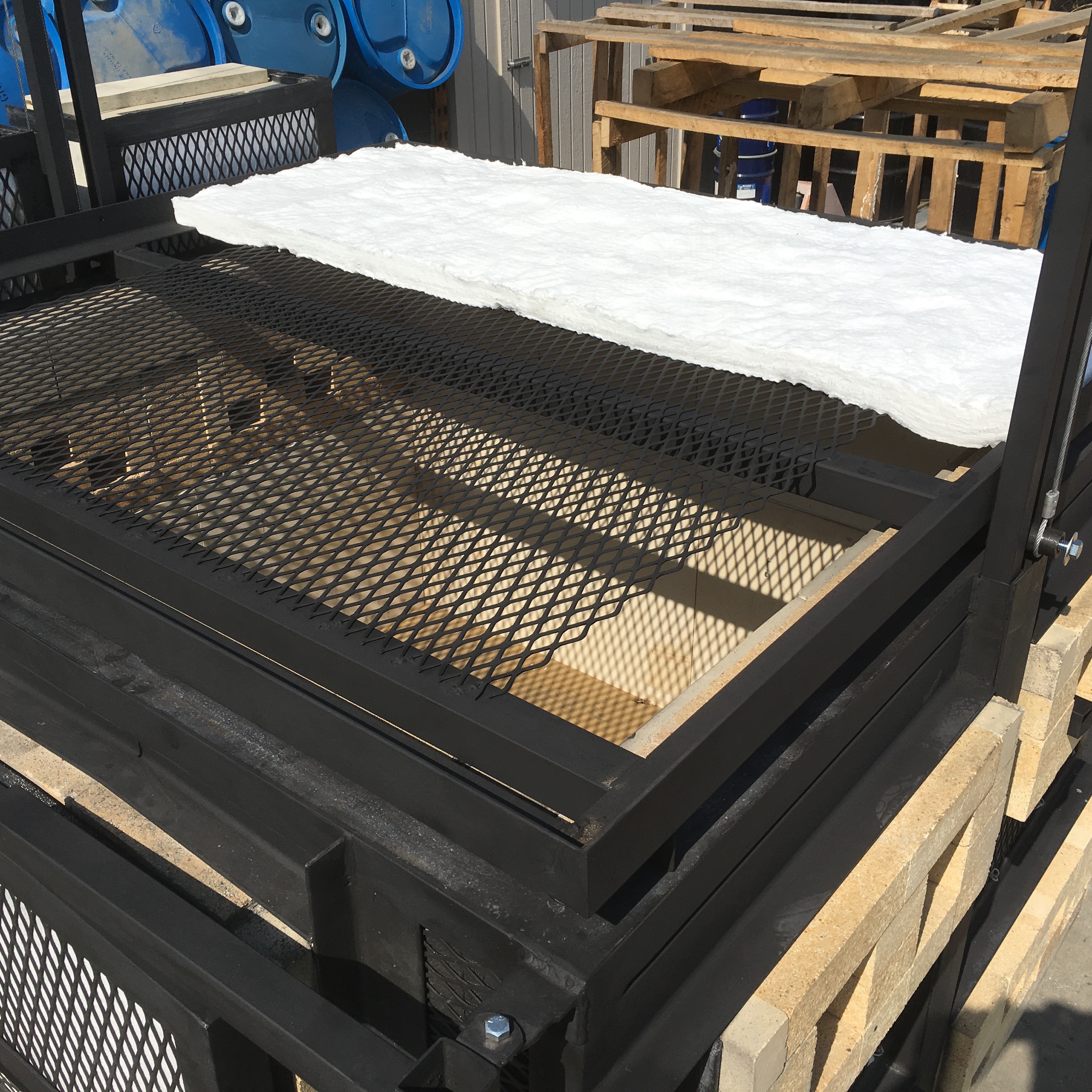
Corelite kiln shelves are cut to fit within the side walls of the kiln. Very little of the fiber will be exposed to the erosion of ash. The shelves are the hot face and hold up very well to erosion. 9 gauge nichrome wire is used to mount these shelves to the lid frame.
This pic of the cross section of the shelves shows the location of the holes to be drilled for the nichrome wire anchors. The holes are drilled on either side of the internal ribs of the shelves.

I weighted down the shelves against the fiber with the help of a forklift and 900 lbs. of clay.

These are the tools I use. The two wire ends are inserted through the shelves and fiber and and are pulled through on either side of a piece of the 9 gauge – 3/4″ expanded metal.

Vertical masts need to be tall enough to accommodate the width of the lid.

The square retainer tube has been removed and the retainer washer and bolt are returned to the pipe to capture the cable. When the lid is raised to the proper height, the pipe/lid will freely rotate within the cable loop to allow the lid to flip over for repairs out in the field. The pipe was hollow and a nut was welded in place to receive the retaining washer and bolt. The square retainer tube has a 1/4 inch rod welded to it that is inserted into a hole in the lid. This along with the large hole in the retainer tube that the fits over the pipe and the two vertical masts, holds the lid level.

Here is a shot of the two larger square tubes that are welded to the frame, flat bar reinforcement cover, and two of the vertical masts that guide the lid.
This is a rain cap made of two pieces of 18 gauge galvanized sheet metal that rest on square tube framing. There has been a little warping of the metal where the two skins come together, so it is best to have the metal folded on all edges to eliminate warpping.
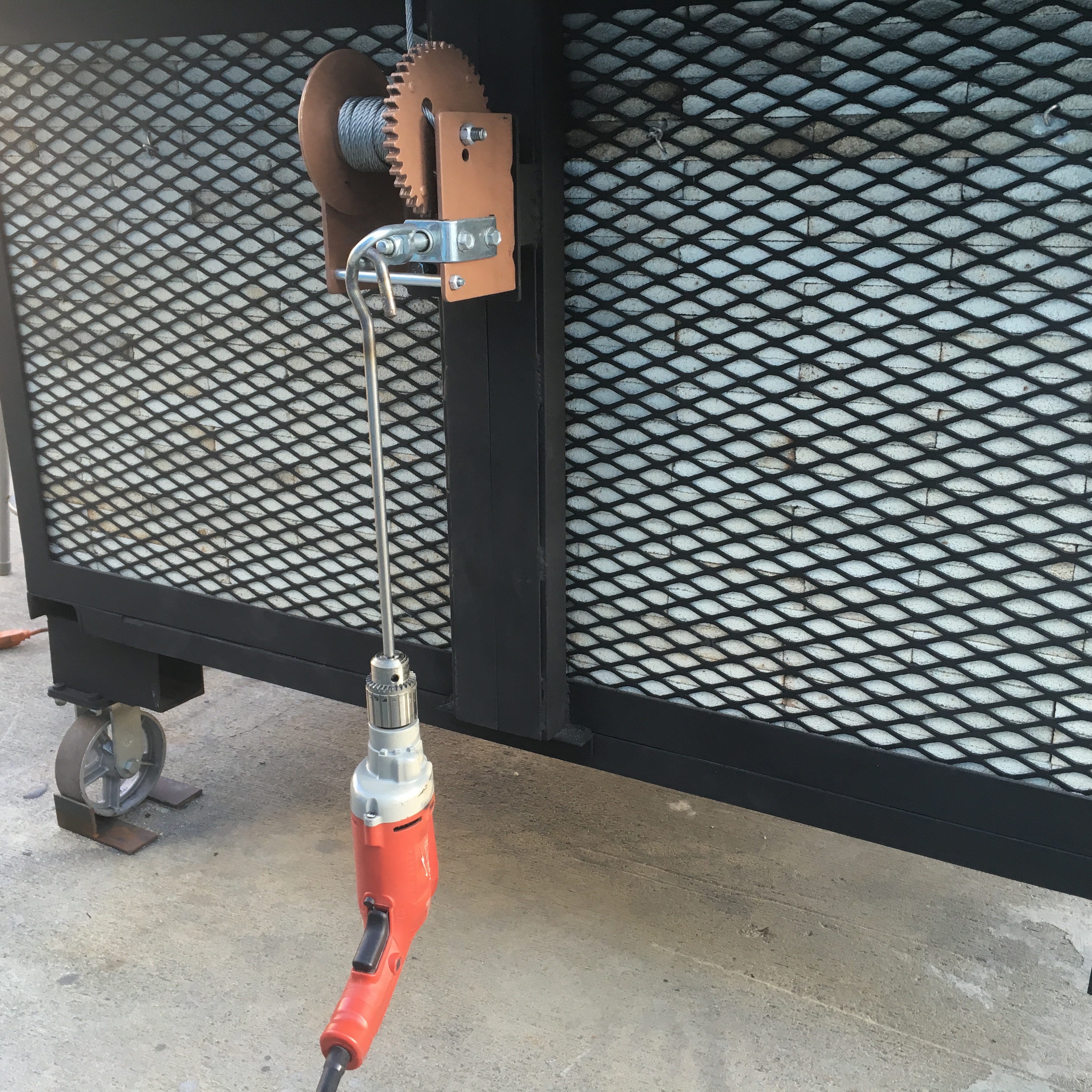
The winch is from Grainger and is a Dutton-Lanson Gear Winch, worm gear, 2000 lb. capacity. Grainger item # 33UD43, Mfr. Model # WG2000. It comes with a loop that can be attached in place of the crank handle. A strong drill motor with a hook is inserted into the loop, which makes quick work of raising the lid.
Stoke Door Construction
Here is a door design that I stole from Zac Spates‘ web site. It is a double hinge set up that allows the door to be pulled away from the opening and then rotates the door’s hot-face away from the stoker.


This is a barrel hinge, but a simple rod or bolt inserted into a drilled hold will suffice.

90 degree weld tabs are welded to the top and bottom ends of the vertical square tubing frame and and these are placed onto angle iron supports (held in place with red C-clamps). Then hole locations from the weld tabs are marked onto the angle iron supports and drilled. Then bolts are dropped into the holes to complete the hinges for the door.

The door frame is constructed to match up with the brick frame of the stoke port.

A layer of ceramic fiber paper is laid against the expanded metal frame and then the ricks are cut and laid in place.

Once everything is all ready to go, the bricks are removed and then mortared into place.

Sairset mortar is applied over the entire surface area of the hot face of the stoke door. This will create a hard surface to protect the soft brick door from abrasion due to opening and closing the stoke door against the hard brick opening. The brick door is held tightly against the metal frame so that holes can be drilled for the insertion of metal pins.

Hole sizes match the diameter of the pins that will hold the bricks into the frame. The location of the holes are in the middle of each brick. The pins are tapped through the frame until flush with the frame. Then the the pins are spot welded and ground smooth with a grinder.
Matching door frame and stoke opening.

The hot face of the door swings away from the stoker.
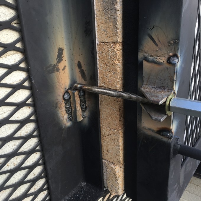
Threaded rod drops freely into a square coupling nut.
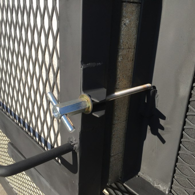
I purchased the door latches from Geil Kilns.
Completed stoke door.
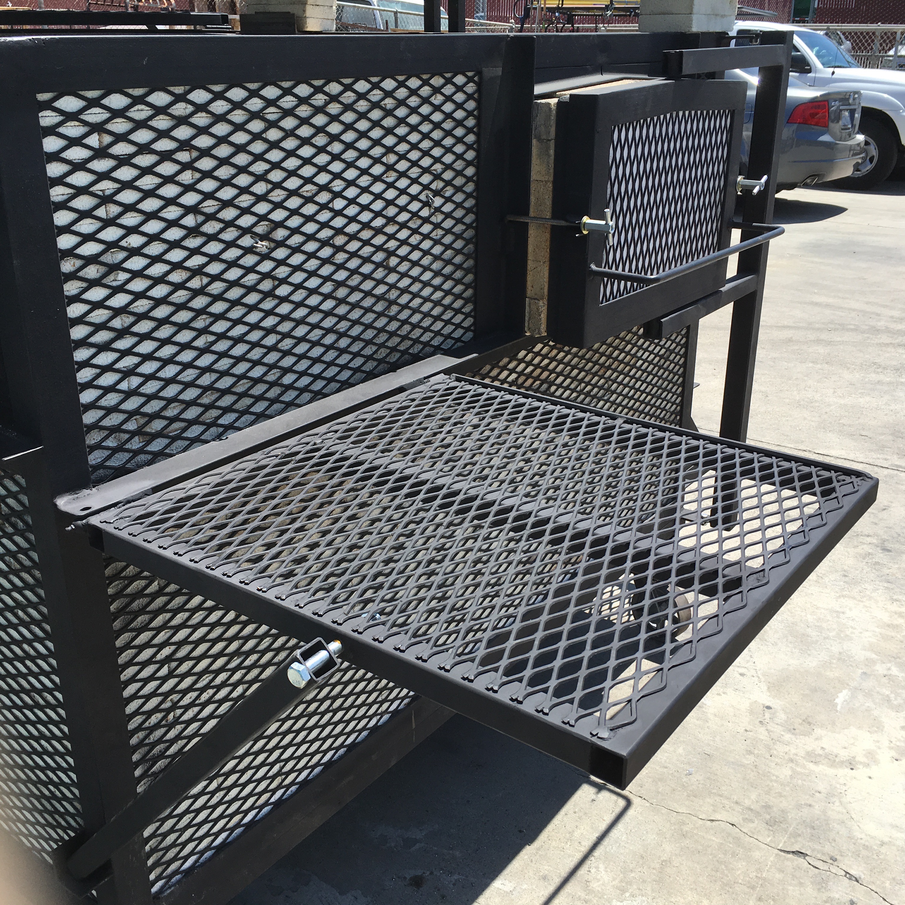
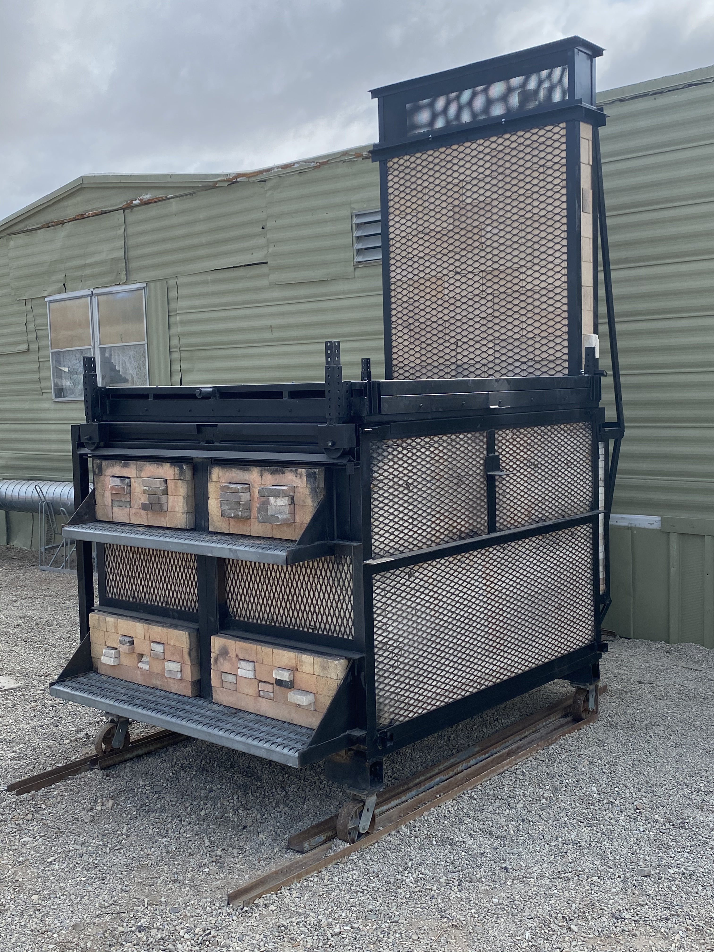
Exterior Grates
The grates were added to support brick decks for pre-heating, holding bricks for plugging air ports and as steps to climb in and out of the kiln for loading.

A metal frame with square tubing acts as the support structure to which the grate was welded to.

The pre-heating can be be done with either level.
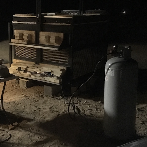
This is a two burner propane set up with a pilot burner for pre-heating.
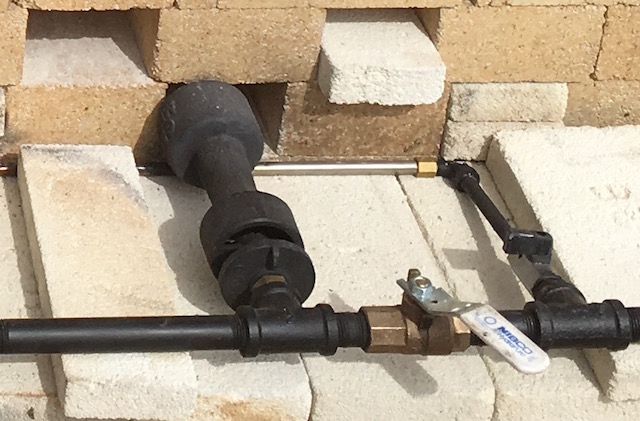
The stainless steel tube of the pilot burner is perforated for air and propane and due to it’s long length, will not burn out under windy conditions. This allows for an overnight candle without observation. This simple burner setup brought the kiln up to 12ooF after 12 hours with 20 gallons of propane fuel.
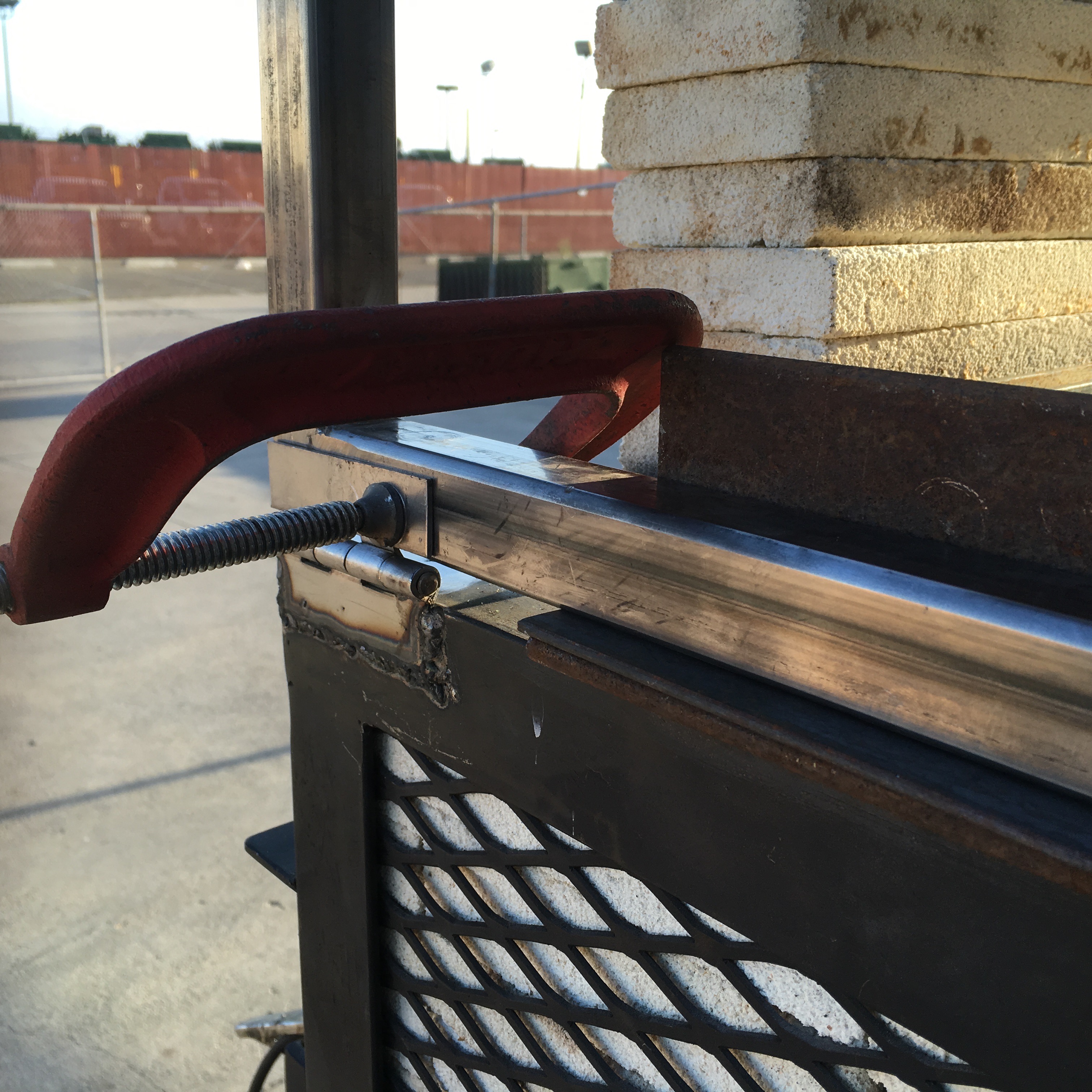
Folding tables
Folding tables were added to the sides of the kiln to make life easier.

This is the stoke table.

Barrel hinges.
The table is held in position with square tubing which rest in place in a piece of angle iron that is welded at the rear corner. The table can be raised and lowered.

This is the loading table being squared before welding.

The loading table drops down flush with the wall.
Fiber Shields

These sheet metal channels cap the walls to cover the 1 inch fiber blanket seals. This keeps down the fiber dust getting into one’s lungs and on one’s skin.

Hard brick ports were sandwiched between boards to keep them from shifting during transport.

Remember how I started off talking about transporting this kiln on my old single axel Kazegama trailer? This kiln came in over 5500 lbs., even with soft bricks in the walls and floor. So here it is on an auto trailer.
The Firings
Wooden 2x4s were used as safety props to keep the lid from lowering while loading.
The inside of the entire kiln was coated with a liquid mixture of 50% EPK, 50% Alumina Hydrate, and 10% Magnesium Sulphate (Epsom Salts). This mixture has done an excellent job of protecting the surface of the refractories.

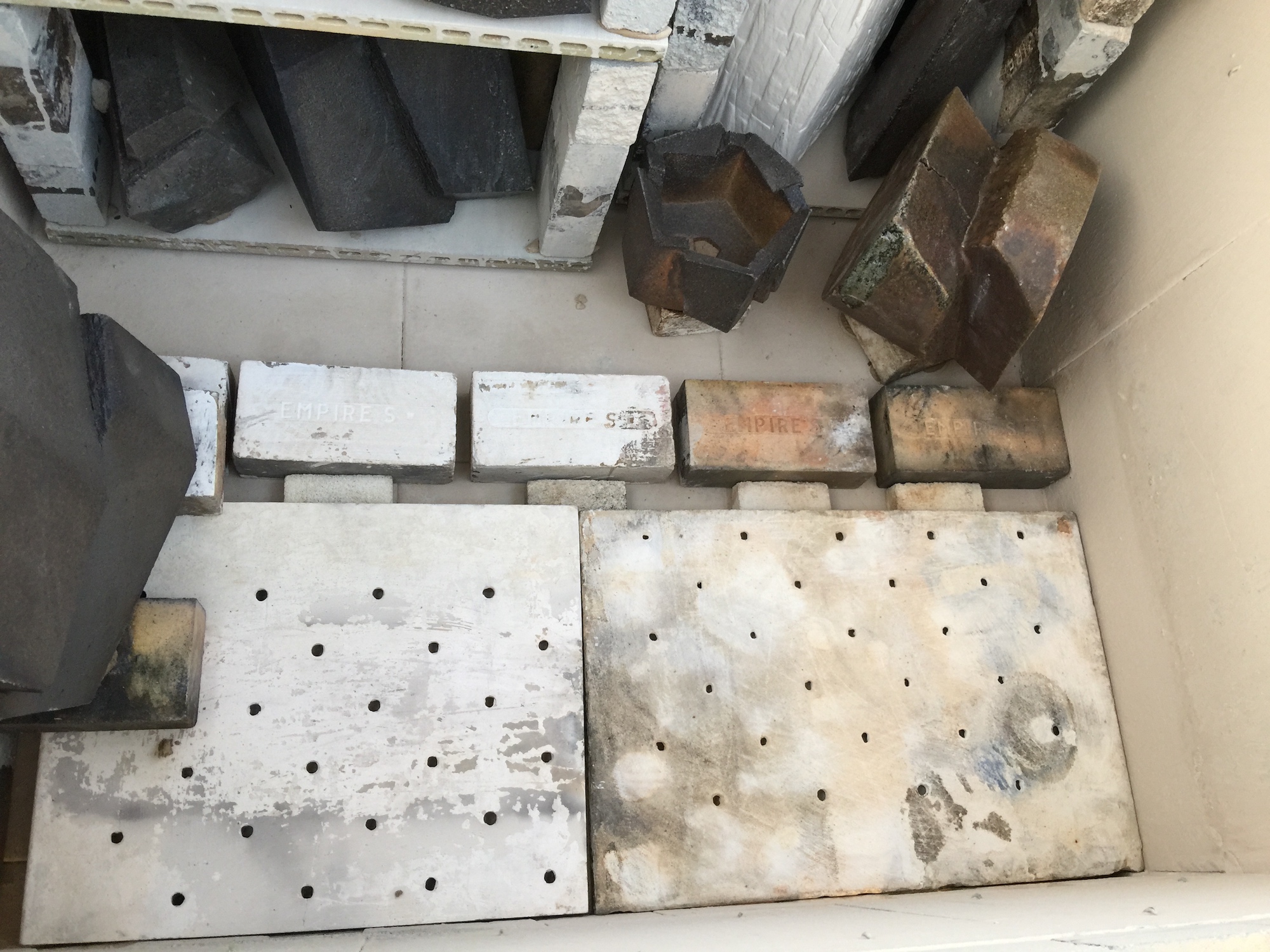
Grate
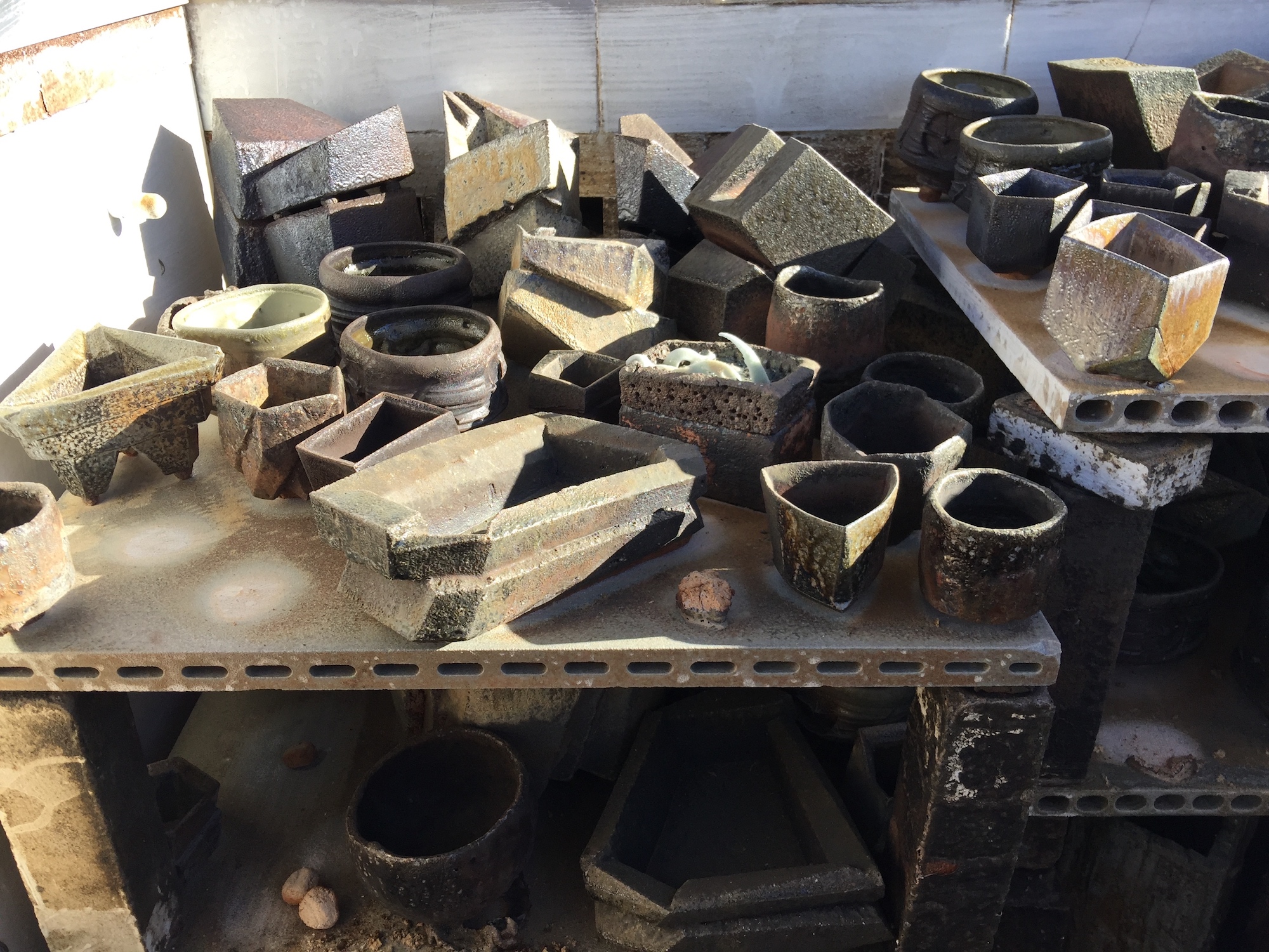
Jonathan Cross refires from the Akagama
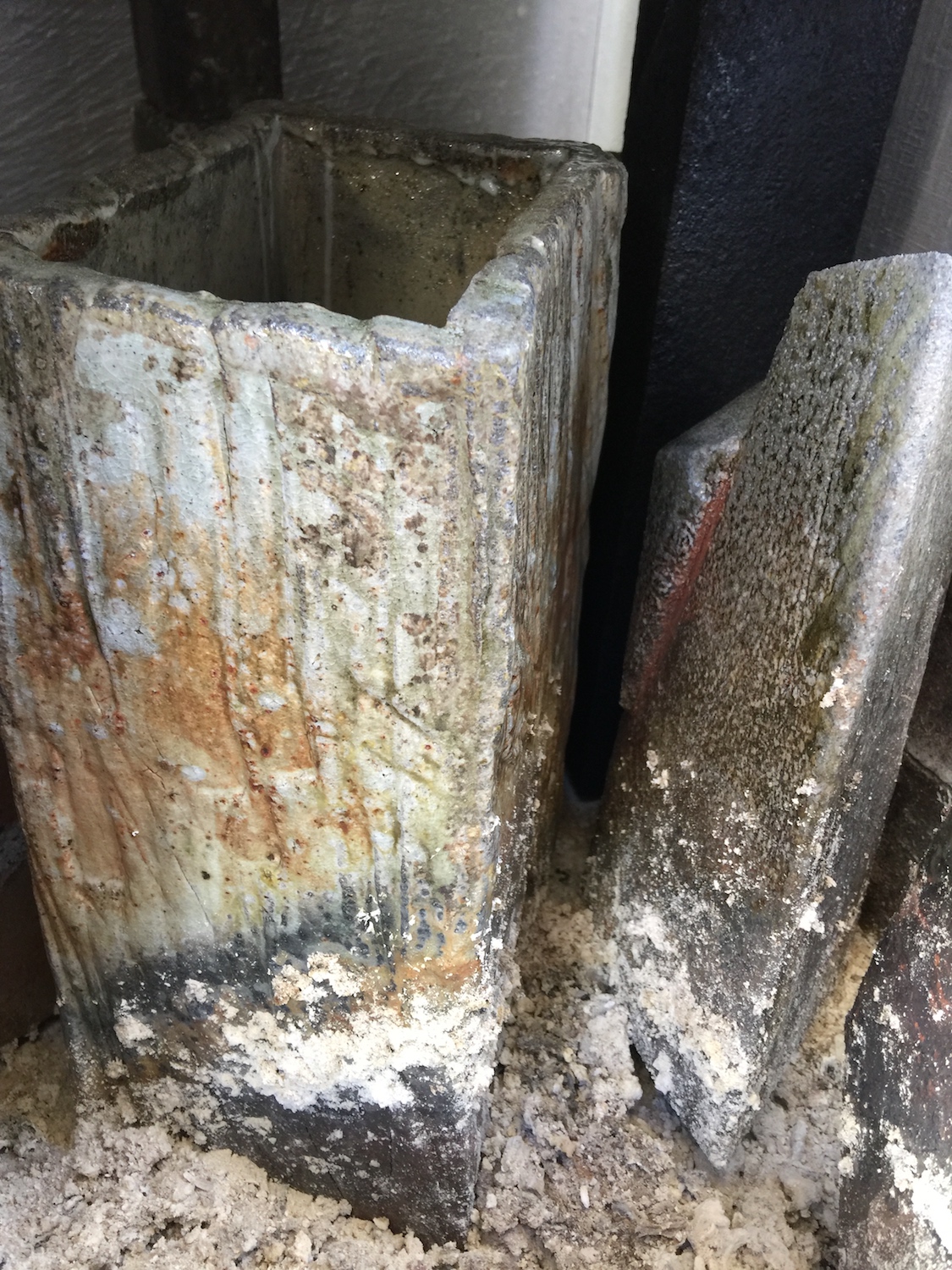
Kaz Ota square vase

Jonathan Cross geometric forms
This design has some flaws in the heat that was affecting the rear lifting cables and there was always lots of labor involved in stacking the chimney bricks.
2021 Modifications of lid and chimney…


I tore out the old chimney, measured out the brick layout, welded up a metal frame, and drilled out lower exhaust ports to bring ash and flame to the bottom of the kiln.


Channel, angle iron, V-groove wheel, telescoping tubing with holes and flat bar make up the track.


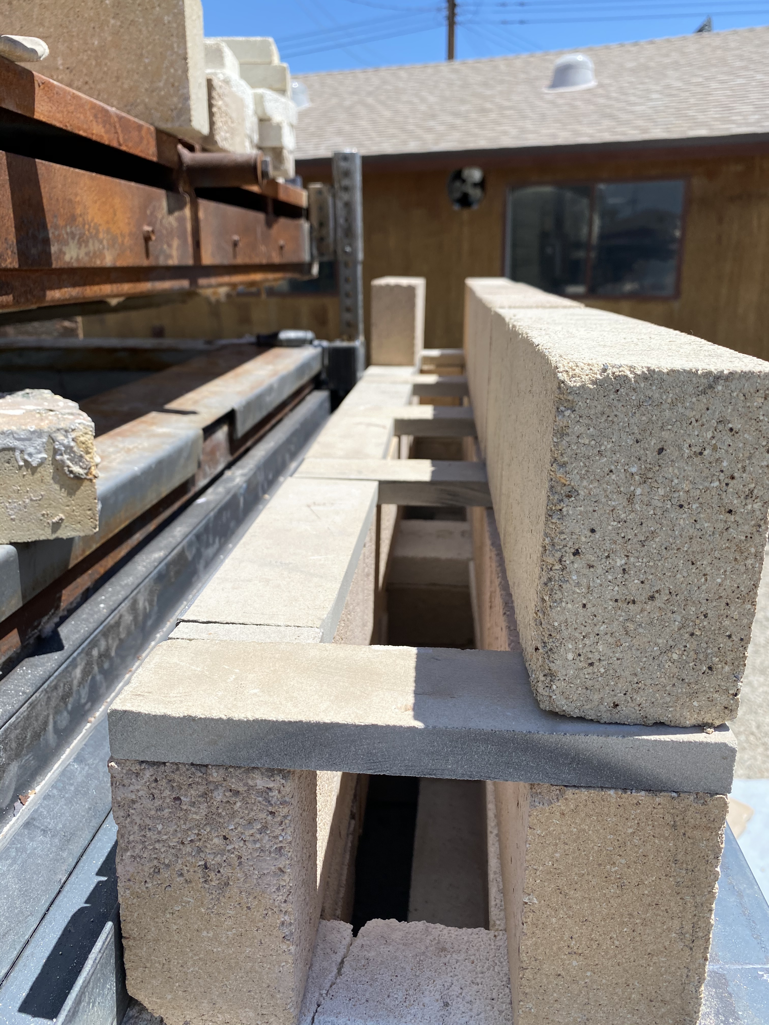
The flue bricks were moved away from the track and flue spacing for dampers established.

Flue slots and rough layout of bricks. This upper chimney bricks (placed on edge) are unstable without expanded metal welded onto the upper frame. An insert of wood has been built that slides into the chimney to maintain the placement of the bricks. It is removed when it’s time to fire.


Kiln shelves can be accessed with this new set up.
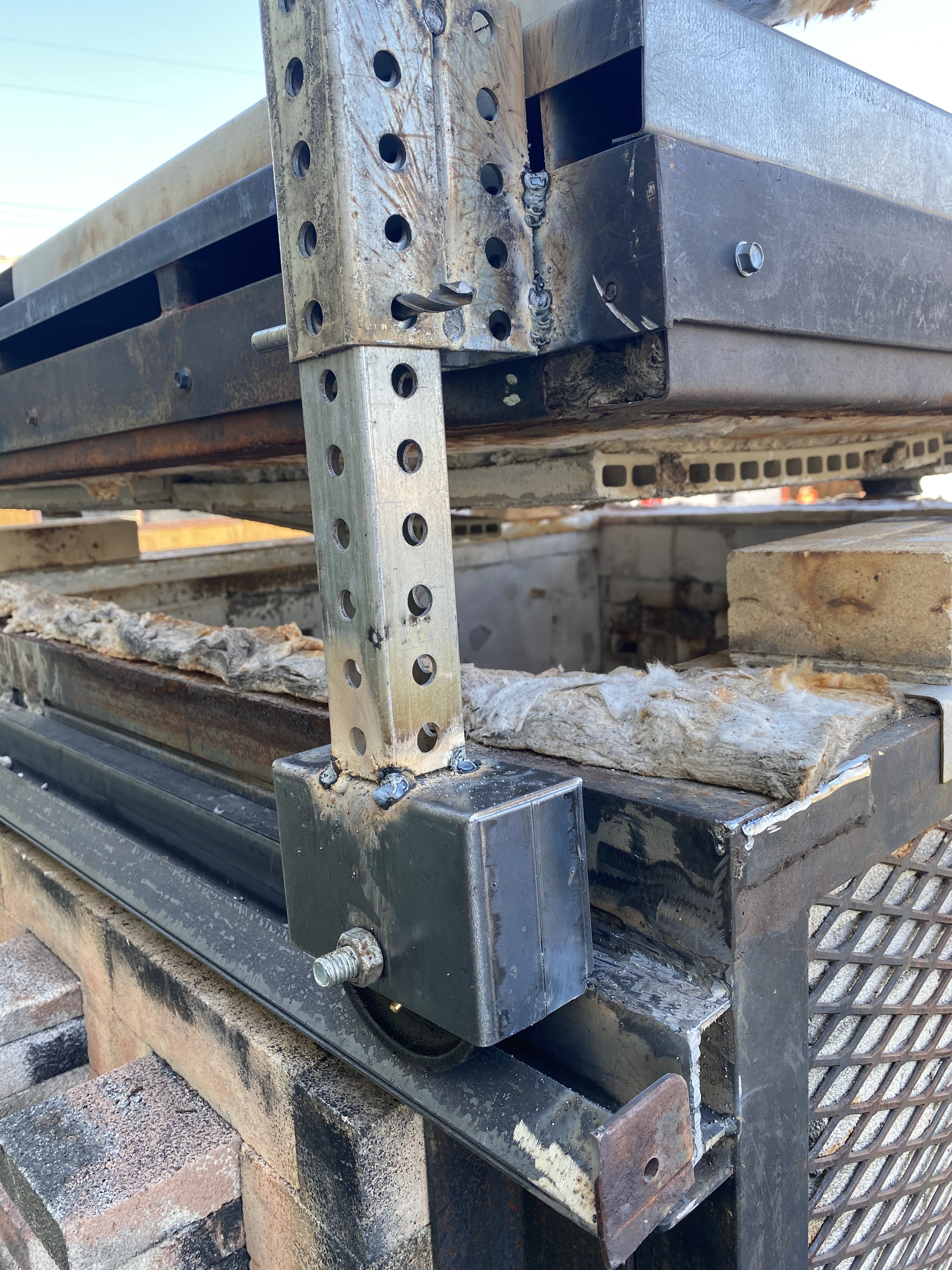
The lid track is temporary and installed/bolted for loading and maintenance. Angle iron is welded onto the lid frame and side wall to hold a bottle jack. The lid is raised by pumping the handle on the ball jack until the lid clears the kiln wall. This is done on both sides of the kiln. This is a very simple and economical method. Height adjustments are held in place by inserting a rod or screw driver through the holes in the square tubing.
Ember screen, rear chimney bracing and expanded metal added to upper chimney. Passive damper bricks are placed on the side of the upper and lower side walls of the chimney. A small opening needs to be added in the front of the chimney above the lid for observing flame in order to time stoking properly. It remains to be seen how this chimney design works.

 copy")


")
")


