
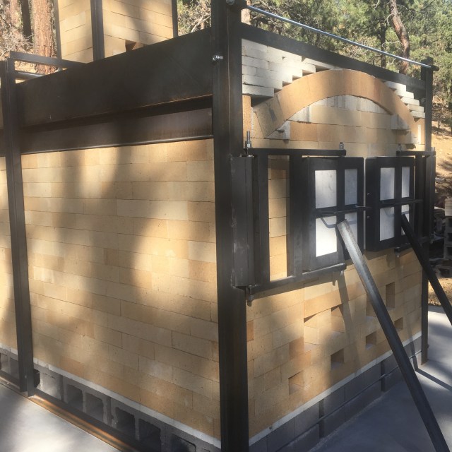
The design is part of a progression in kiln designs that I base on the placement of wares in close proximity to the firebox and ember bed. The footprint of the floor for wares and ember bed is 4 feet by 4 feet, with 2 feet of depth for the ember bed and 2 feet of depth for wares and shelving. The inside height from the top of the grate to the center of the arch is 45 inches. The interior space is greater than 50 cubic feet.
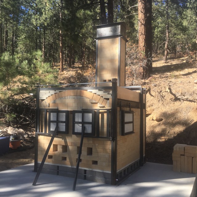
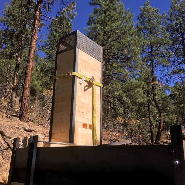
The kiln sits on 15 tons of concrete at 8200 feet of elevation above the town of Durango. The winters are very cold and due to deep freezing, require a rather thick concrete foundation. On top of the concrete is a layer of cinder blocks, followed by a layer of K28 soft brick splits and then 3 inch hard brick shapes from Alsey Refractories out of Alsey Illinois. For this project, we used Jet DP high duty fire bricks. Most hard bricks in the US come out of this single brick plant as a result of consolidation in the refractories industry. The sales contact for potters is John Koprevich of Nittany Minerals and he can be reached at 814-360-9040. John can also arrange shipping with major shipping carriers. Alsey Refractories has a fantastic assortment of different brick shapes including large square edge tiles for stoke door lintels, wedges, feather edges, splits and standard brick shapes.

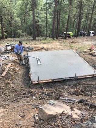


Delivery on a country road required a tractor with forklift assembly. Rich Weigman at the wheel….He did a great job of pouring the concrete slab and many other tasks.
The Floor, Grate, Back Wall and Lower Chimney

K-28 soft brick splits were used above the concrete cinder blocks for a layer of insulation between them and the hard bricks in the floor.
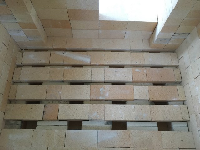
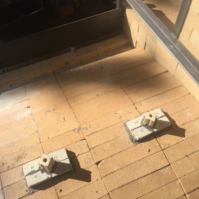
A very stable grate can be achieved by cross hatching bricks over the primary air troughs and then locking them in place with brick spacers. This creates a very stable grate that will not move or break when logs are thrown onto the grate. Thanks to Jonathan Cross for this design.
The lower chimney is as wide as the rear wall of the kiln. This creates a more even distribution of flue gases and ash throughout the entire width of the kiln.
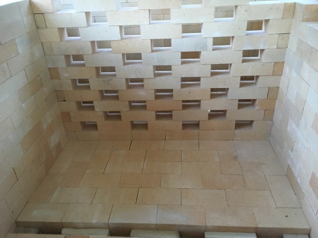
The holes in the honeycomb pattern can be filled with bricks to regulate the flow of heat and ash. The temperature at the side walls can be three cones cooler than the area just inches away due to heat sink from the 9″ walls, so the outside holes are generally open and the middle holes are blocked in an every-other pattern.
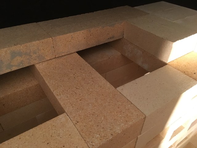
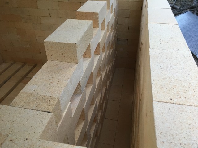
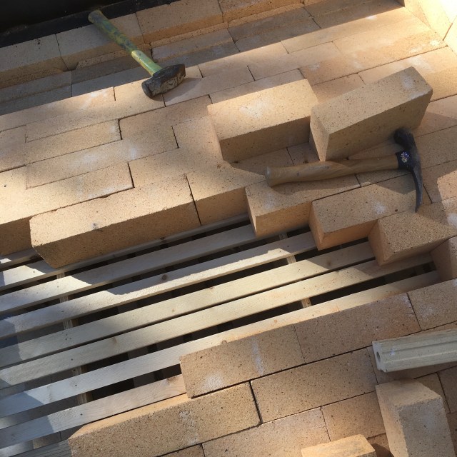
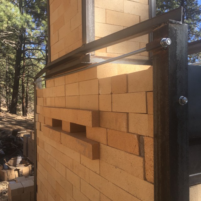
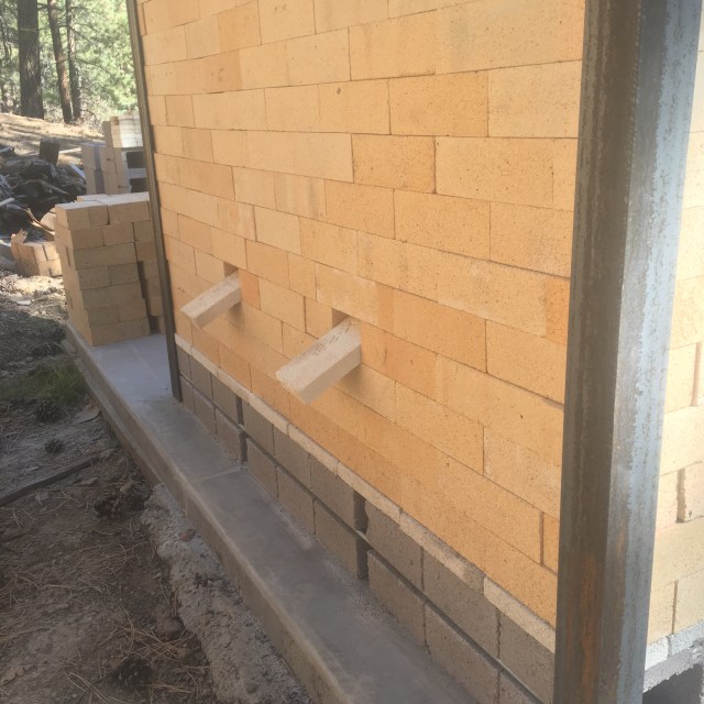
18″ x 4.5″ x 3″ bricks help span the 9″ depth of the chimney. This shows two openings for placement of the flue shelves that are 9 inches wide by 18 inches long.
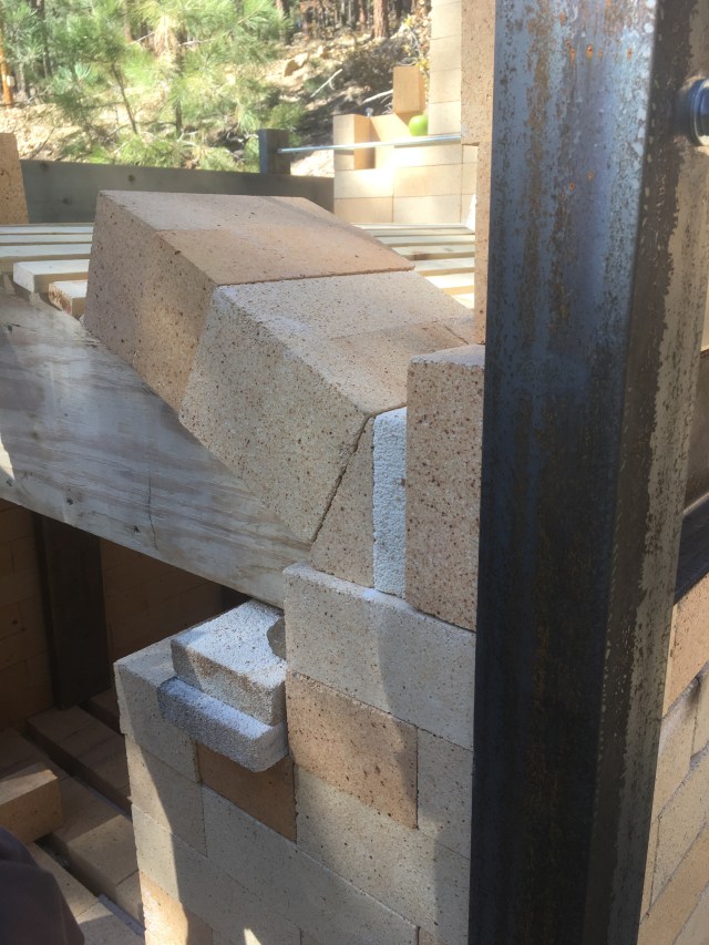
This is the top of the lower chimney section. Instead of stacking a corbeled arch, I capped the outside shoulders of the lower chimney with a flat top on either side. The bricks that are two bricks from the top and two bricks from the side measure 18″ x 9″ x 3″ and support the top row and the upper chimney section (not in place).
Four primary airports are shown beneath the grates. Arch bricks are in the foreground.
The Arch
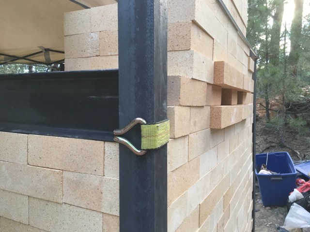
3″ angle iron was used to capture the corners of the kiln and retain the 6″ channel.
A shipping strap is a great tool for pulling in the framing and brick work before welding.
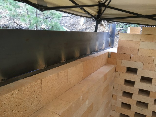
The 6″ channel is shown under a piece of 9″ tall x 3/16″ plate steel. The 6″ channel supports the arch and will be supported by an I beam and angle iron at the corners.

Arch bricks need to have equal pressure against the entire surface of the brick face so that the arch stays true and bricks don’t slip out of place. So I like to place the bricks onto the surface of plywood sheeting to layout the bricks with full contact, and then trace the bottom of the bricks with a black marking pen. This becomes the template for cutting the arch frame. This makes for good surface contact between the bricks when they are placed onto the arch form. I also measure the span to make sure the outside edges of the bricks that rest on the feather edges will be setting on top of the side walls and are around a half inch inside the hot face edge of the wall. Here I am using 3″ – #1 arch bricks along with 3″ straights against feather edges. Straight bricks were used at the outside edges of the arch span to achieve the right angle leading into the feather edges. The feather edges need to be squared to the kiln wall and channel that supports the arch.
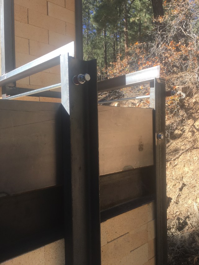
1/2″ threaded rod is inserted into the angle iron metal work. Note how the rod is slotted into the grooves of the cinder blocks. This makes for a nice, clean front wall.
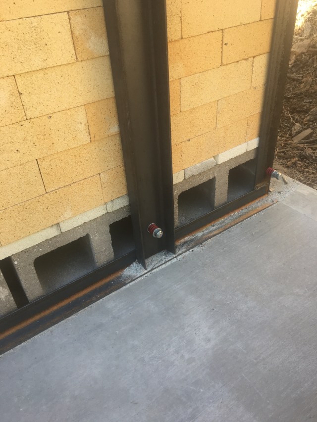
Gene wanted to use threaded rod with expansion springs, so I found these (die springs) at the local hardware store. It takes quite a bit of pressure to compress these.
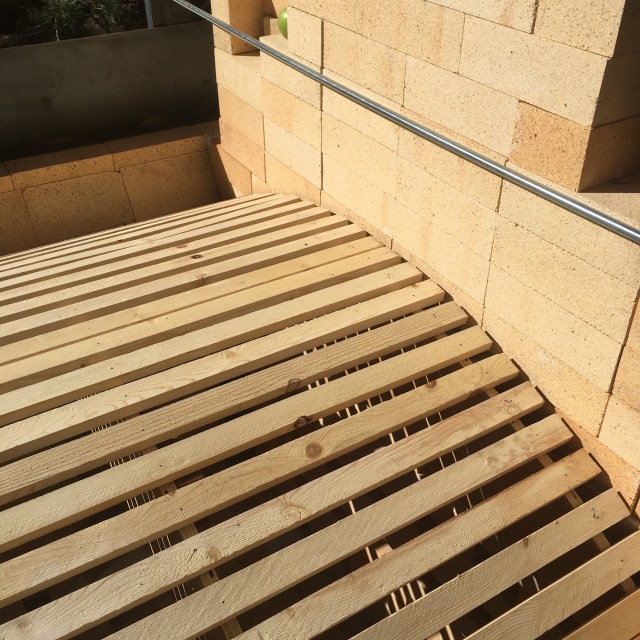
For the arch form, 1″ x 2″ slats were held in place with finishing nails. The bricks for the chimney were stacked to match the height of the 9″ plate steel to contain the secondary insulation the will cover the arch bricks.
One coarse of arch bricks were laid out to decide on the thickness of the soft brick splits set behind the featheredges so that the key brick would tap in with just the right amount of snug fit.
Originally, I designed the arch to be a bonded arch using 13.5″ and 9″ long – #1 arch bricks. But after the arch form was pulled, many of the 9″ bricks started dropping from the arch. As it turned out, the 13.5″ bricks were a tad wider and made it impossible to continue with a bonded arch.
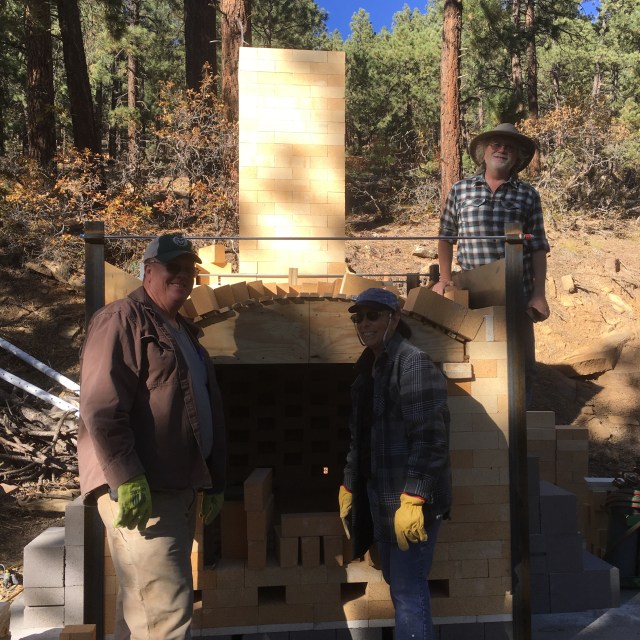
Wayne Petefish (left) of GJ Clay in Grand Junction came down for two long days and was a huge help. I can not thank him enough….To the right is Sue and Gene Killian. This kiln build took two trips. We were joined by Rich Garrett during the first trip who made the 32 hour trip up and back from Southern California and put in three long days. Thank you Rich!
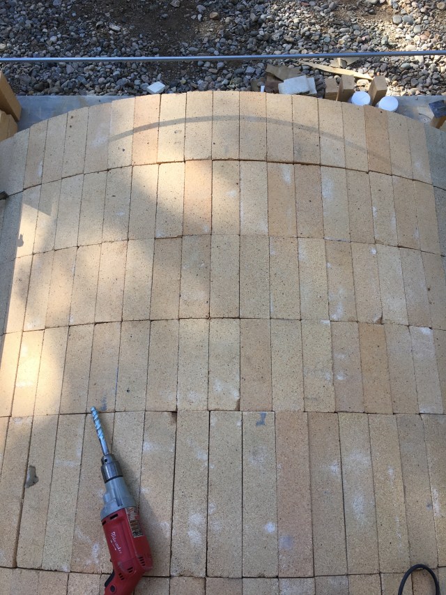
Since the bonded arch was not working, we switched to a ring arch. A 5/8″ masonry drill was used to drill two holes through the 4 corner junction of the center arch bricks for the placement of holes for flame reading and a pyrometer.
Gene matched up the holes in the arch with the holes in these kiln posts and mounted them with soft brick splits and Sairset mortar. 1″ fiber blanket will be placed over the arch to seal the gaps between the bricks. Then layers of soft bricks topped with decomposed granite will be built up to the level flush with the 9″ plate steel and bricks.
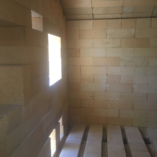
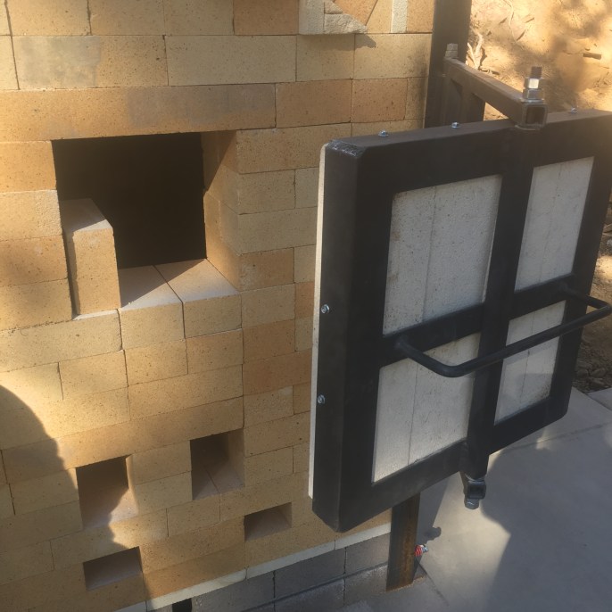
View from the side stoke door.
The Stoke Doors
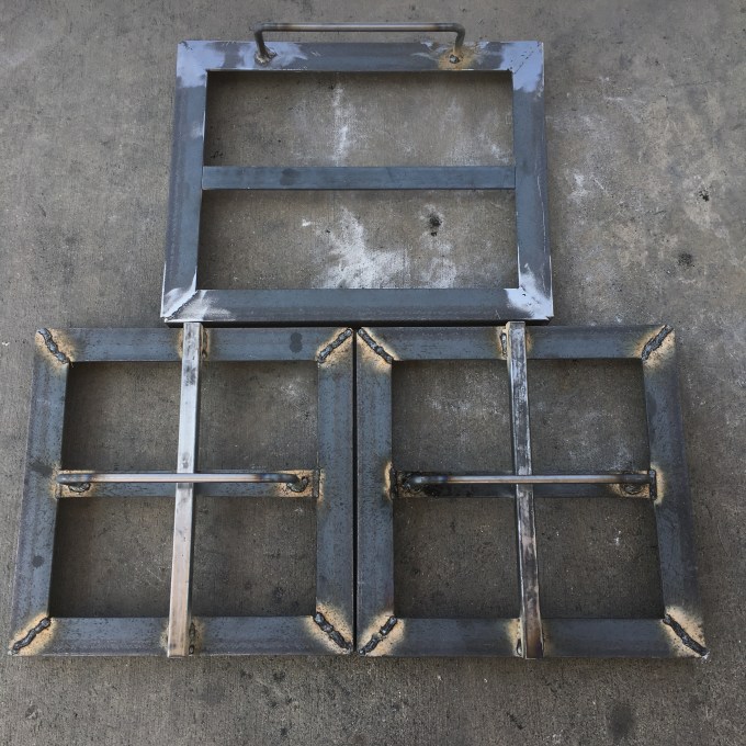
There are three doors on this kiln. The two bottom doors are for the front doors and the door on top is for the side stoke door.
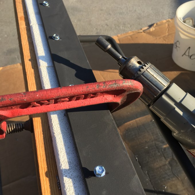
Bricks are held in place with self tapping screws. I used to drill holes, insert 1″ long rods and weld them in place. Then I realized I could just drill a starter hole that matches the drill bit of the self tapping screw, and then drive the self tapping screws into the metal frame and into the bricks. The screws are 1.5 inches long.
Here is one of the front stoking doors. A piece of half inch electrical conduit ( not shown) is placed inside of the 1″ square tubing to act as a bearing between the threaded rod and the square tubing.

Here is the door assembly with threaded rods. The angle iron on the far right will be welded to the corner of the kiln frame after the front doors are bricked up and the exact location of the doors are ascertained. Washers are used between the door and bracket.
The white soft brick splits will be mortared in place above the arch or castable may take it’s place. This will contain the fiber blanket, soft bricks and decomposed granite that will make up the secondary insulation above the arch.
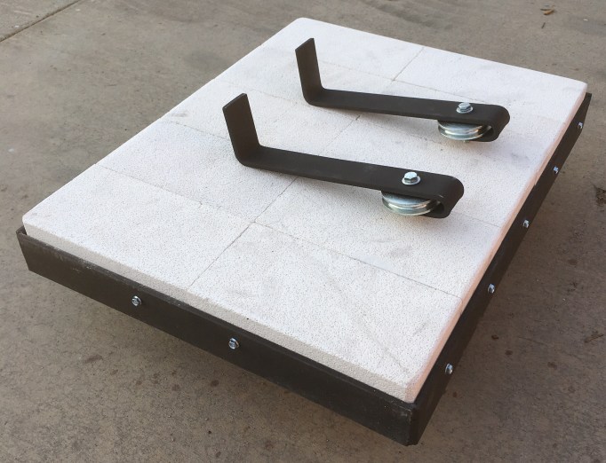
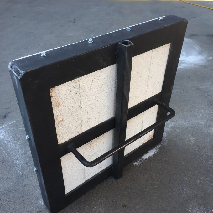
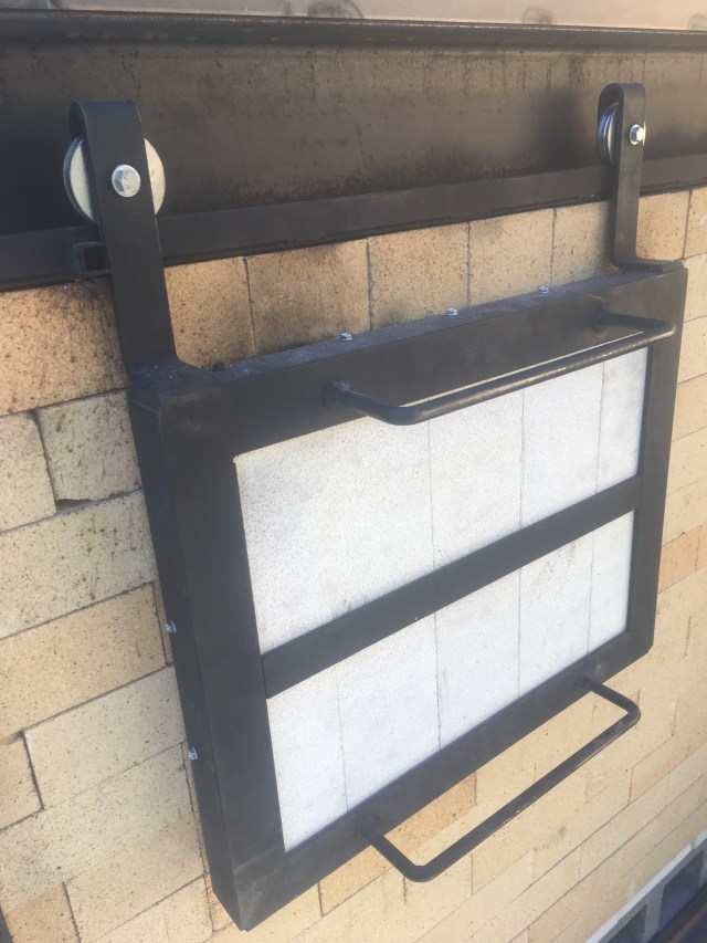
Here is the “barn door” for the side stoke port. The two hangers with wheels will be welded to the metal frame when the 1″ flat bar wheel track is installed and the door is placed up against the opening of the stoke port.
The hanger length had to be shortened and then welded once the proper placement was ascertained. The first welds are spot welds and the wheels are checked for squareness in relation to the 1″ flat bar track. Then full finish welds are applied. Small square tubes were welded where the door stops and starts.
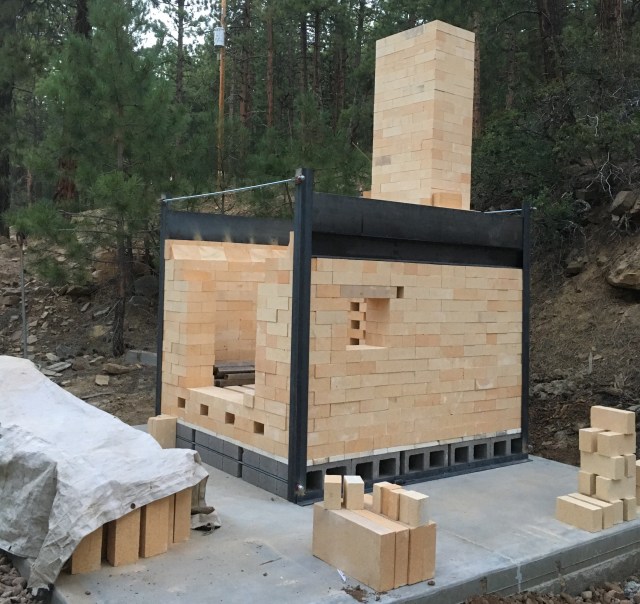
Three stoke doors. It was fun employing two styles of doors on the kiln. There was not enough room in the front for barn doors because of the travel distance required to clear the stoke port openings. The bottom 4 ports are the primary air ports that feed under and through the grate. The upper 4 ports are above the grate and are for secondary air running over and/or through the ember bed. Another port that will be used for secondary air, a viewing port and for introducing small pieces of wood for reduction cooling will be located just under the center of the arch between and above the two front stoke doors.
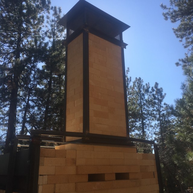
The Chimney and Ember Screen
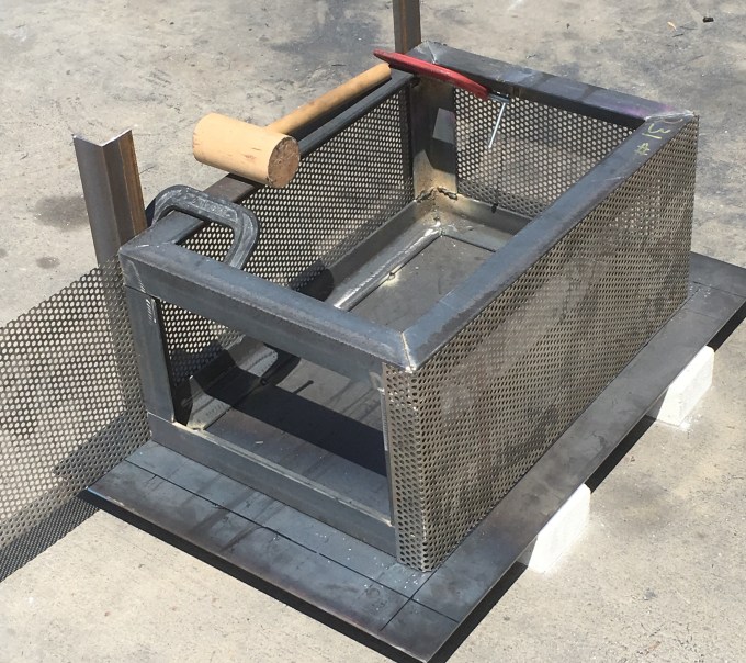
The frame of the chimney screen is made of 1/4″ – 2″ angle iron. The cap is laid down with the frame centered on top of it. The cap and frame are spot welded together to secure the cap to the frame so that holes can be drilled through both the angle iron frame and cap. The 1/4″ mesh screen is secured to the frame with a C-clamp and formed around the corners of the frame by hand and wooden mallet.
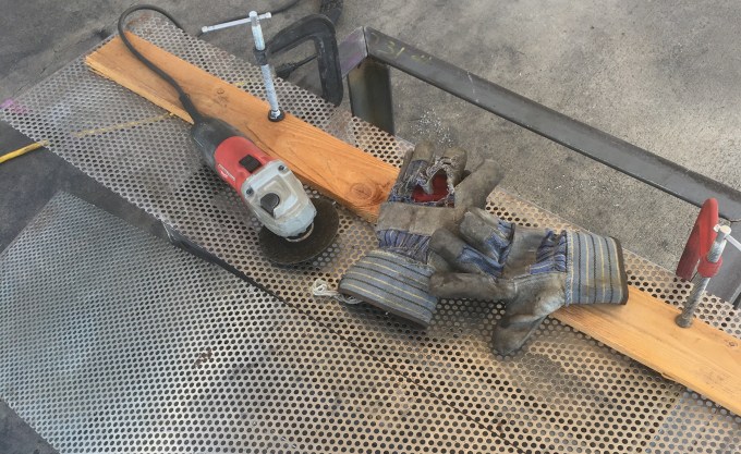
The 1/4″ mesh screen was cut to 12″ in width with a hand held grinder and cutting wheel.
Stainless steel bolts are placed into the holes and welded in place.

The holes in the cap were enlarged to ease the placement and removal of the cap over the stainless steel bolts. Over several firings, the cap is going to warp, so it is wise to have a little wiggle room in the bolt holes.
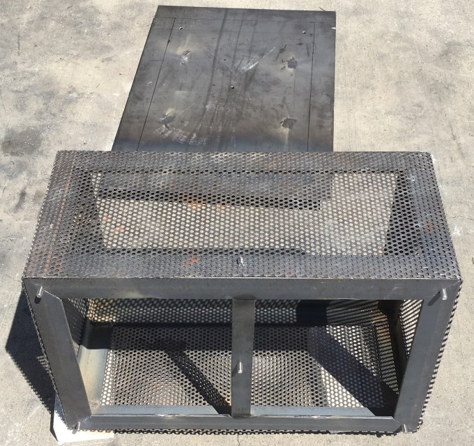
5 foot lengths of 2″ angle iron made up the corner supports for the chimney. The two rear corners come up 3 inches above the bricks to capture the screen when slid into place. Then a piece of 2 ” angle iron is bolted in two places to secure the screen. A bolt in the center is drilled in a downward direction to receive a 2″ bolt. This holds the screen in place on the metal frame so it will not be lifted out of it’s footing from wind or an earth quake.
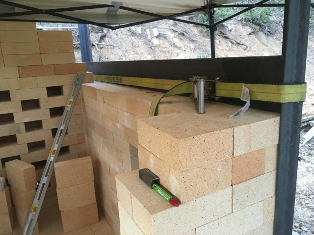
Shipping straps were used to hold the 2″ angle iron frame in place for spot welding

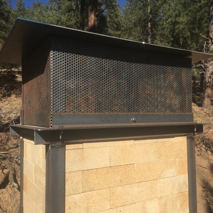
Bricks were placed over the left and right shoulders of the lower chimney and built up to the 9″ plate steel. I did this to maintain equal pressure across the length of the kiln. 2″ angle struts were welded across the front and back of the chimney and locked into the frame. Is was an aesthetic choice for supporting the 5 foot height of the upper chimney frame. I didn’t want to run struts from the 9″ plate to the top of the chimney frame.
Here are the threaded rods, die springs and chimney frame struts.
Two damper slots to house the 9″ x 18″ dampers. Note the square tubing that has a flat surface for welding onto the 3″ angle iron. It receives the threaded rod.

Two passive damper slots to add oxygen to the flue gases, smoke and embers before they exit through the screen. I love the look of raw steel and brick….
Passive dampers in back of the chimney. These ports can also be used for the placement of MR-750 burners for preheating the chimney to help kick-start the draw of the chimney. The MR-750 burners can be purchased through Aardvark Clay & Supplies where I work.
This was a really fun kiln build. Next comes the completion of the arch insulation, a covered structure to protect against the elements and firing the kiln.

 copy")


")
")


STEVE, If this kiln fires as good as it looks, you’ll get amazing amazig pots from it. The design looks like it will produce amazing results.I have been a potter for 65 years and not seen better !!!!
Bill Merrill bill.merrill704@gmail.com
hey! didnt notice a door for loading wares, wheres it at?
good lookin kiln, interesting design
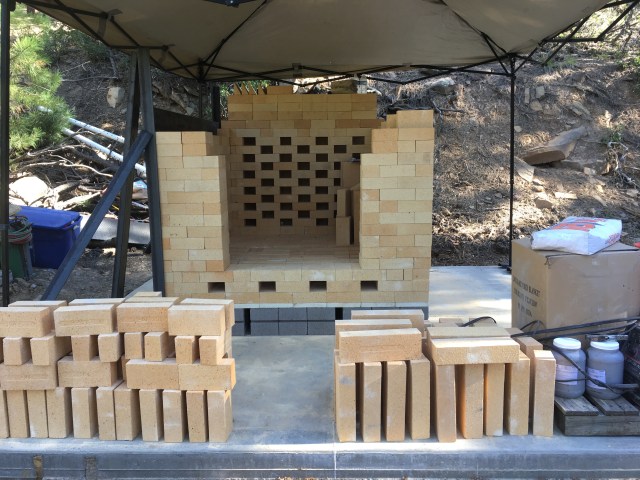
The front wall is unbricked. It allows for changes in air input through the front.