
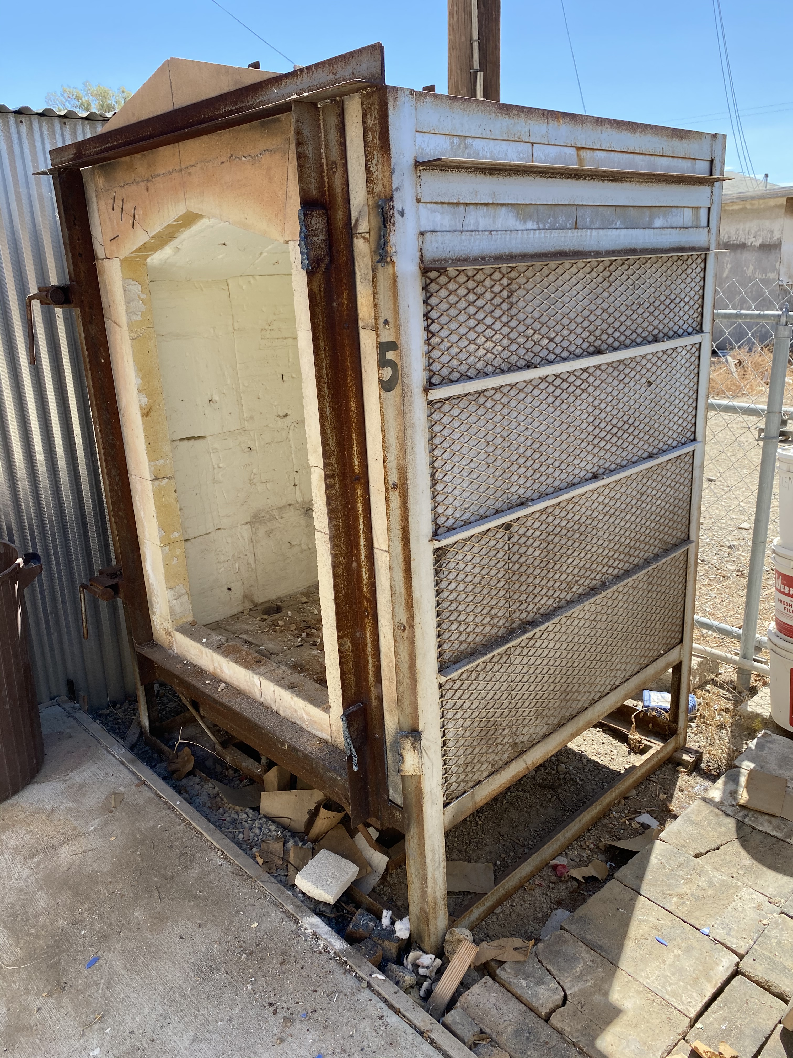
The Lotus Kiln was built for Bombay Beach Arts and Culture (BBAC) in the small town of Bombay Beach, CA off the eastern shore of the Salton Sea. Three years ago, we acquired four used West Coast kilns for $200 with the idea we would create a second life for them . This Lotus Kiln is one of many types of kilns we have at BBAC. Influences for this kiln are Nina Hole’s Fire Sculpture kilns and John Roloff Kiln / Furnace Projects.
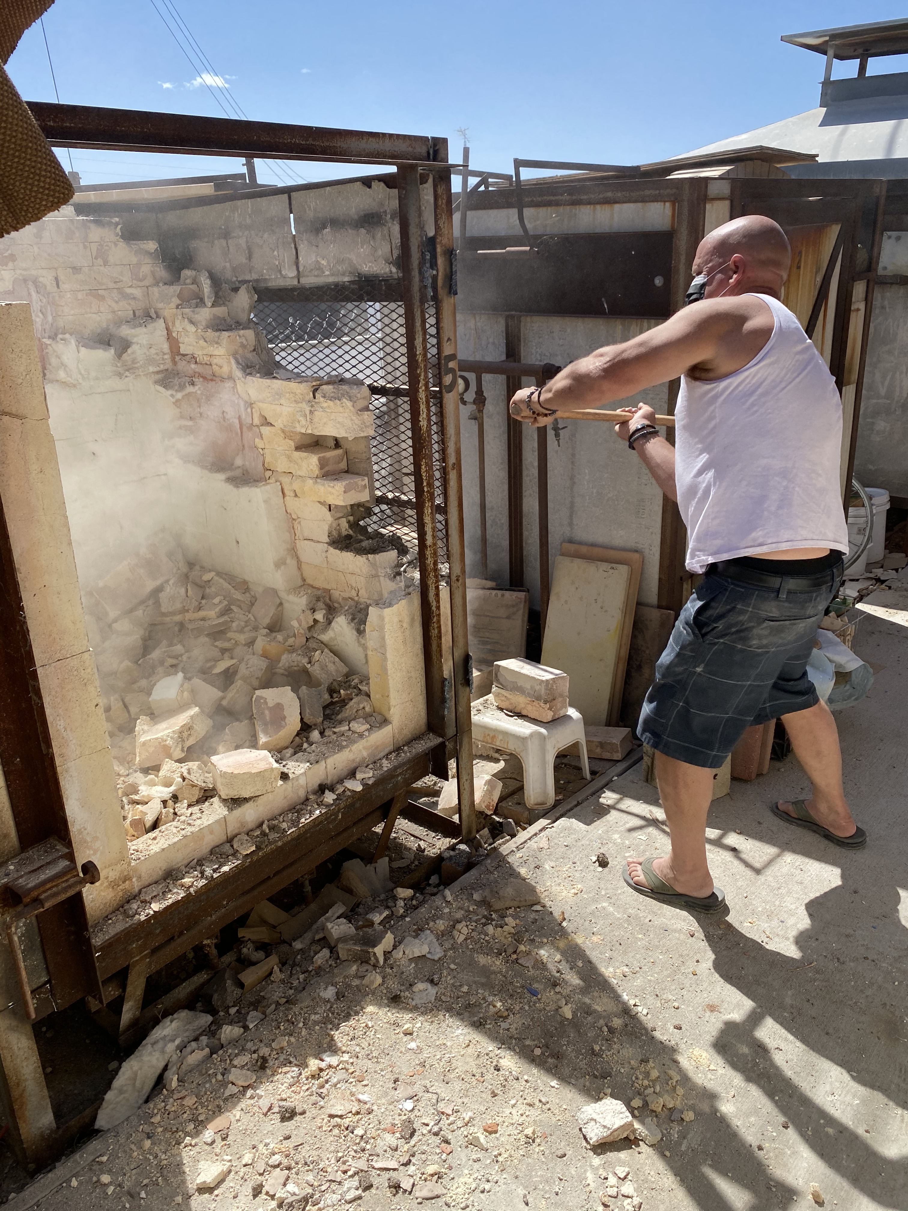

My friends in Bombay Beach included Rob Quinn and Thomas Rhodes doing the dirty work.


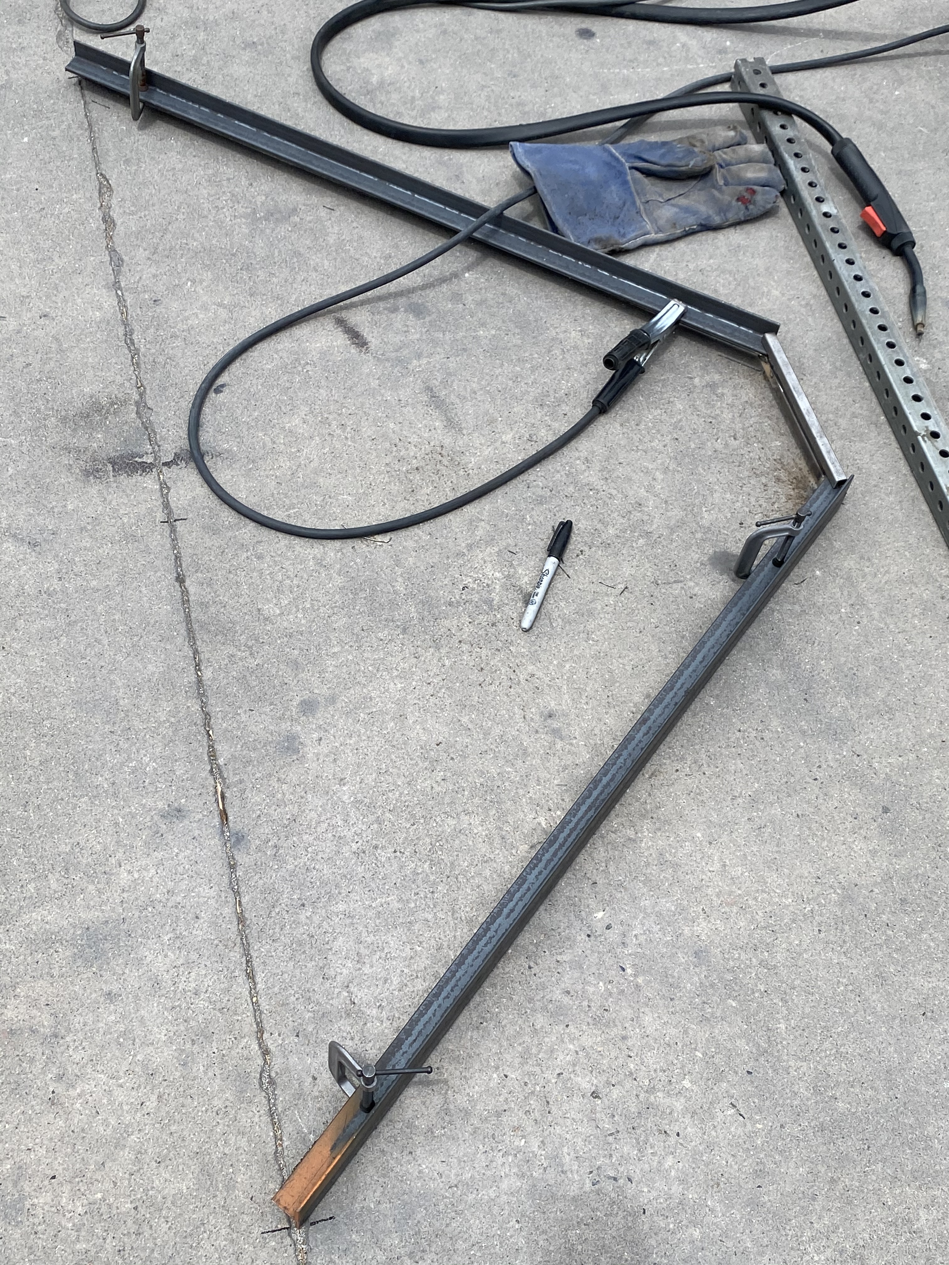
The original burner manifold was too narrow and I had to build a wider replacement. This required the removal and repositioning of the floor angle iron.

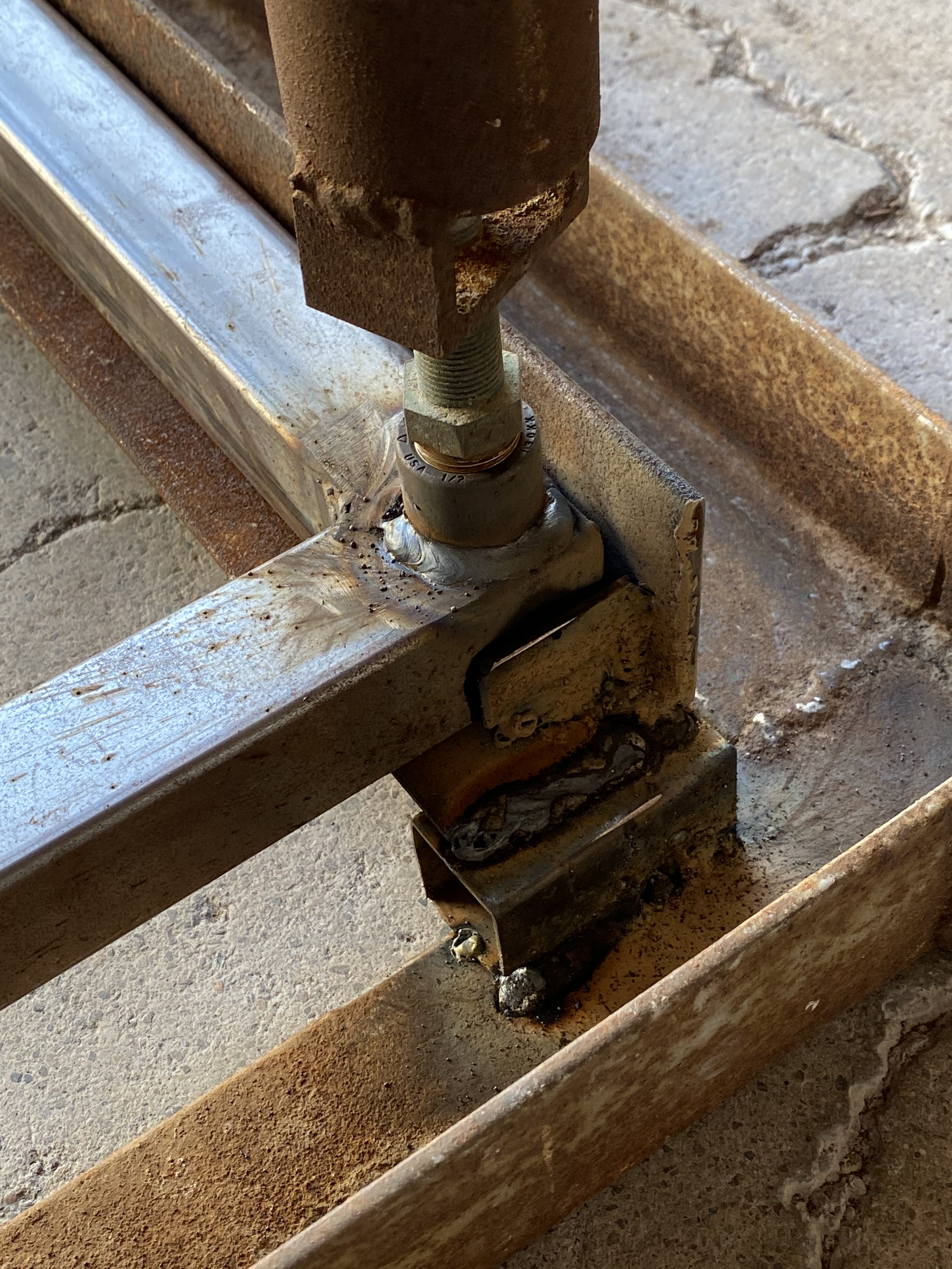
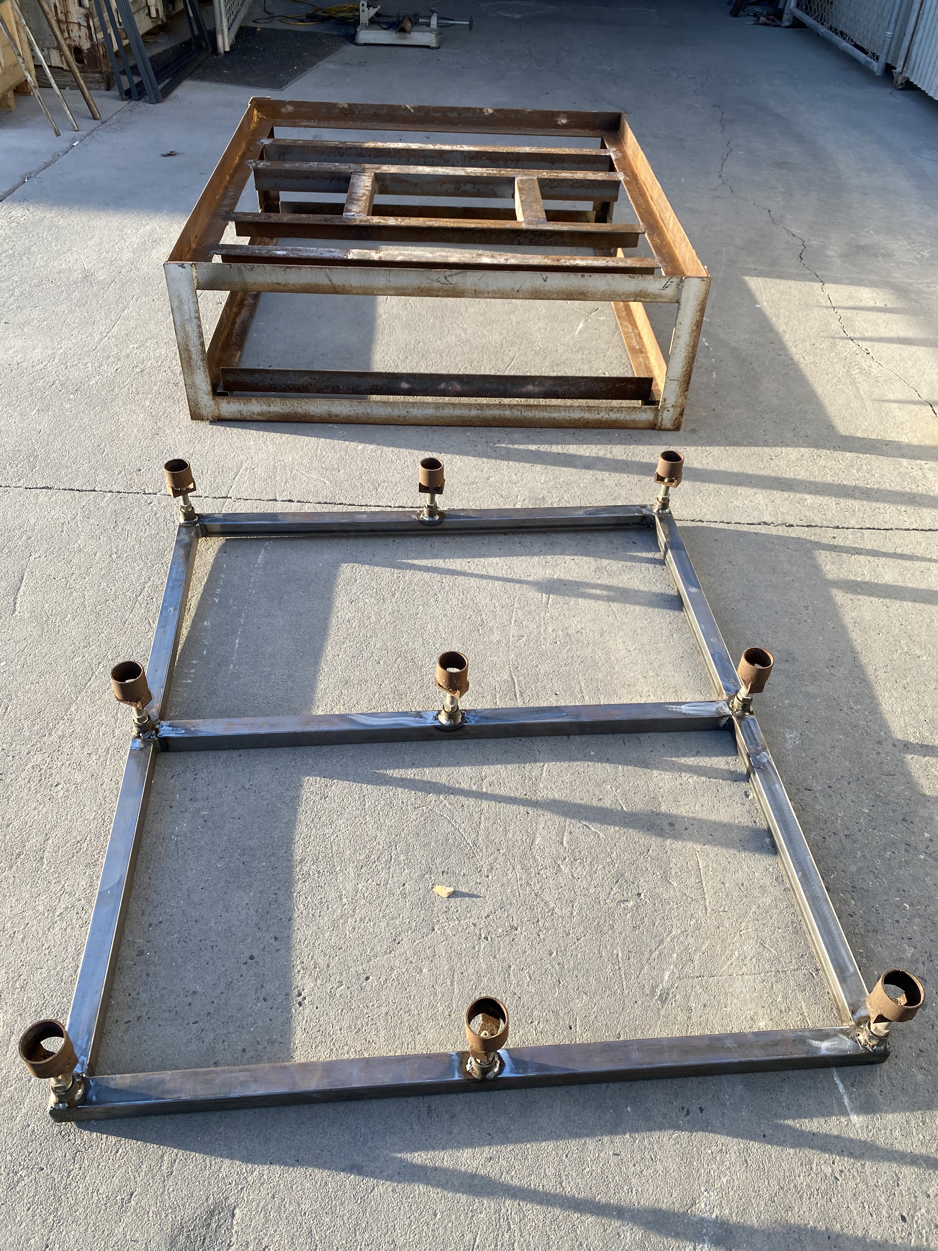
The manifold slides onto two angle iron tracks and has metal stops that keeps it in position to line up with the burner ports in the floor.
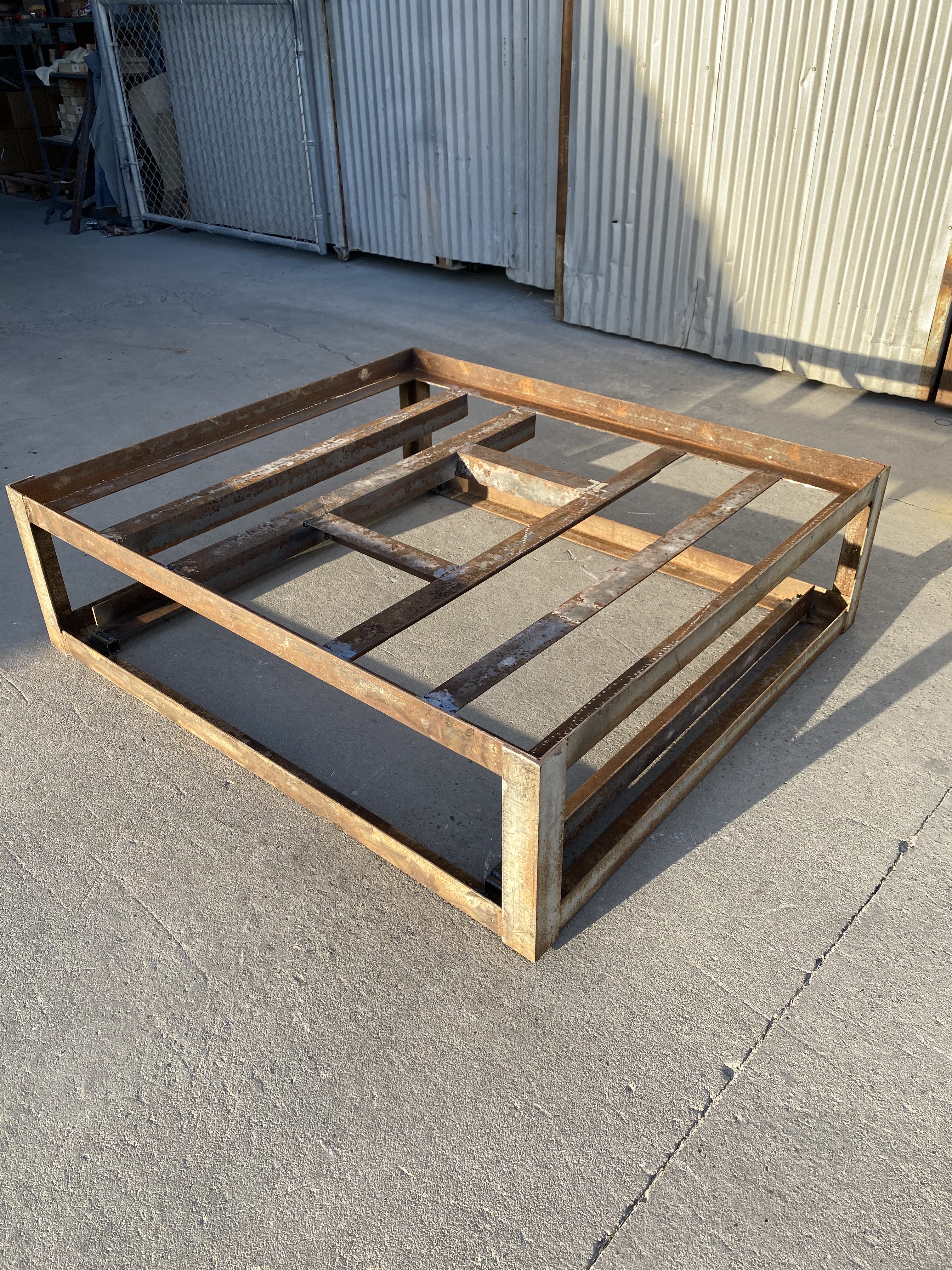

A square frame was built into the middle of the floor to support the expanded metal floor while also creating room for a pipe flange that will be attached to a blower. Ash and other coloring/sparkle agents can be blown up through the sculpture through the flange.

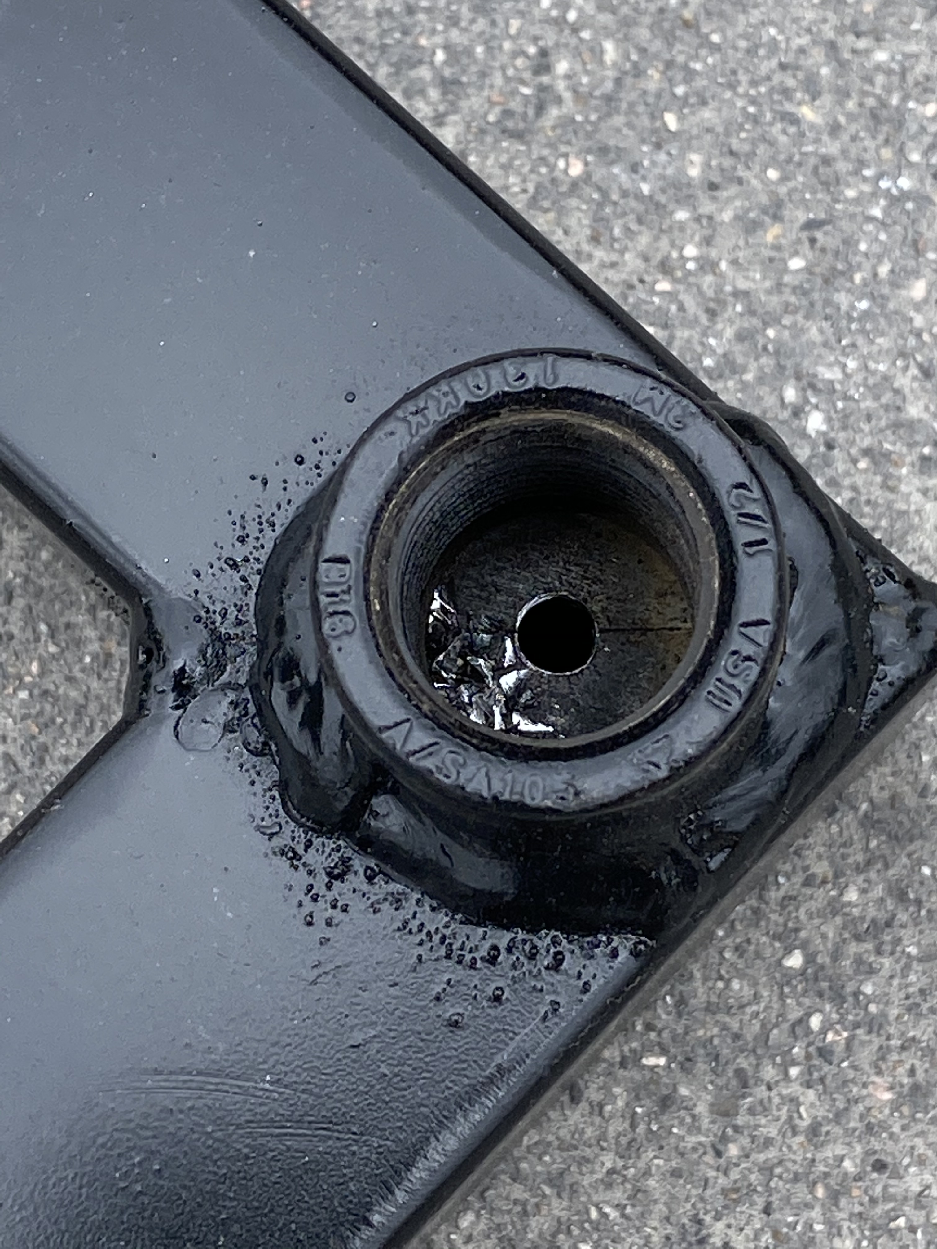

Holes in the weld on pipe fittings are sized to be small on purpose so it is easier for the manifold to load up with gas pressure and have the volume of gas equal throughout the manifold for each burner.
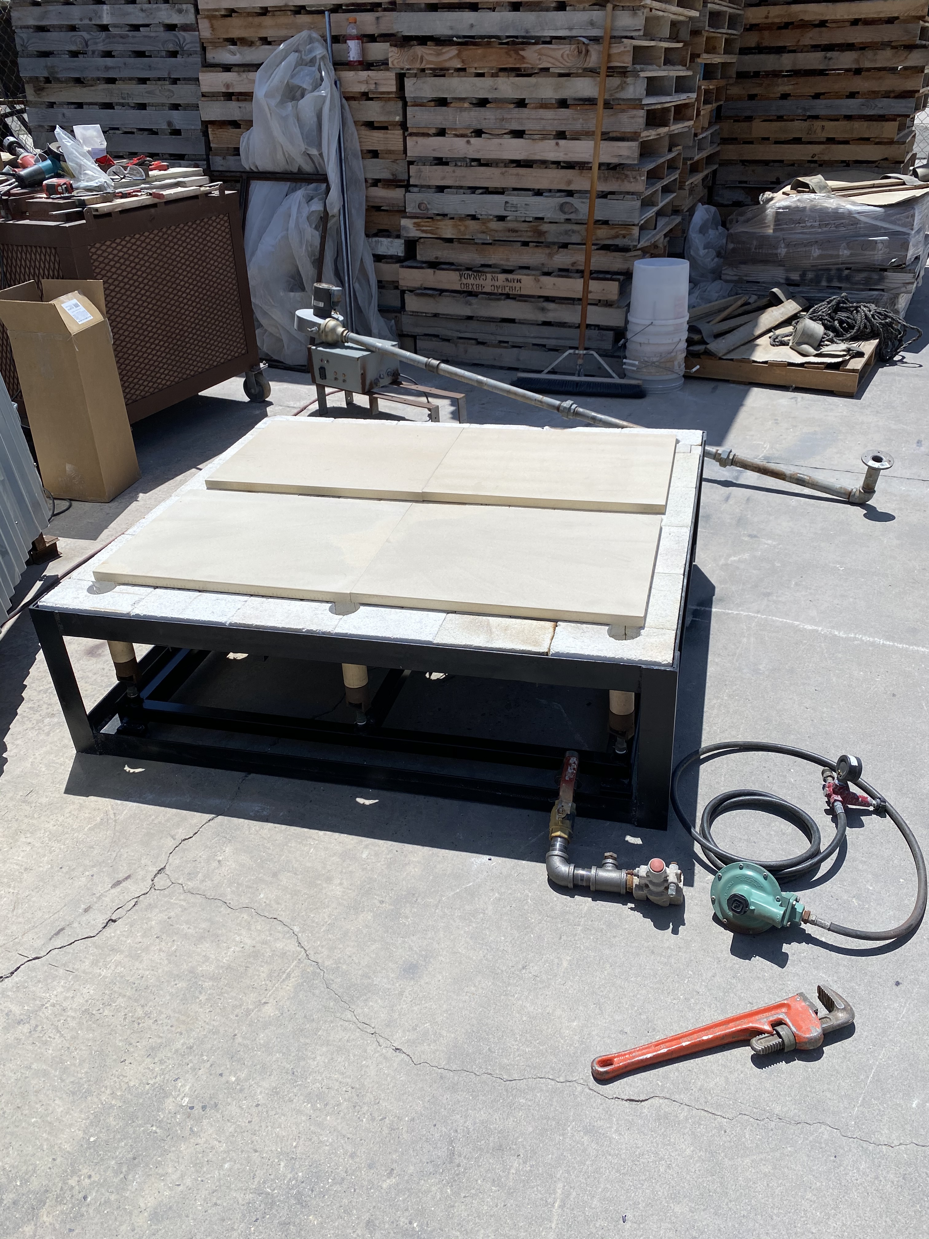
This uses high pressure propane through a 10-foot hose to a Fisher step-down regulator. The output of the regulator is around 11-13 inches of water column pressure (low pressure). Then the gas travels through a BASO low pressure gas valve that includes a port that supplies gas to a pilot. A 1/2 inch copper pipe is soldered around the outside edges of the burner tubes to deliver flame for ignition. It is a completely closed square with a 1/2 inch tee that comes off where the safety hardware/pilot burner are located and slides onto a 1/2 inch copper coupling. The copper pipe is held in place with 15 gauge nichrome wire butany good wire will do. A picture of the assembly is forthcoming. I like to lay everything out at this stage to see what shelf dimensions I will need. There is 2-1/2 inches of soft brick in the floor, so a layer of 1 inch fiber blanket is placed across the entire floor under the shelves for additional insulation. Burner port holes are cut through the fiber.

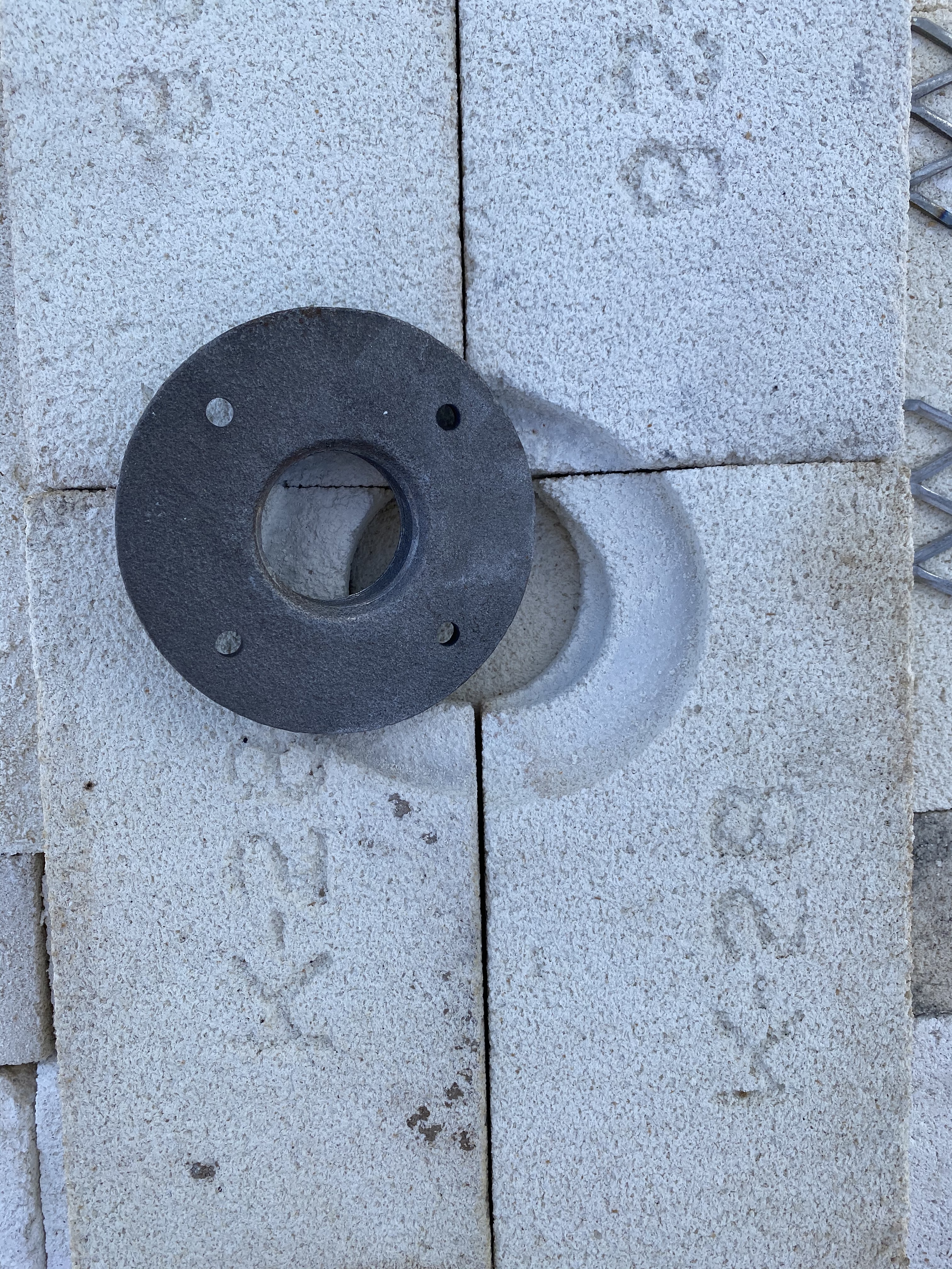

The pipe flange in the center of the floor is tack welded to the expanded metal. Before this is done, the flange is twisted and ground into the soft brick to make it sealed and set back from the heat as much as possible.


1/2 inch copper pilot is drilled with #70 drill bits every 1/2 inch or so, a pain in the ass….
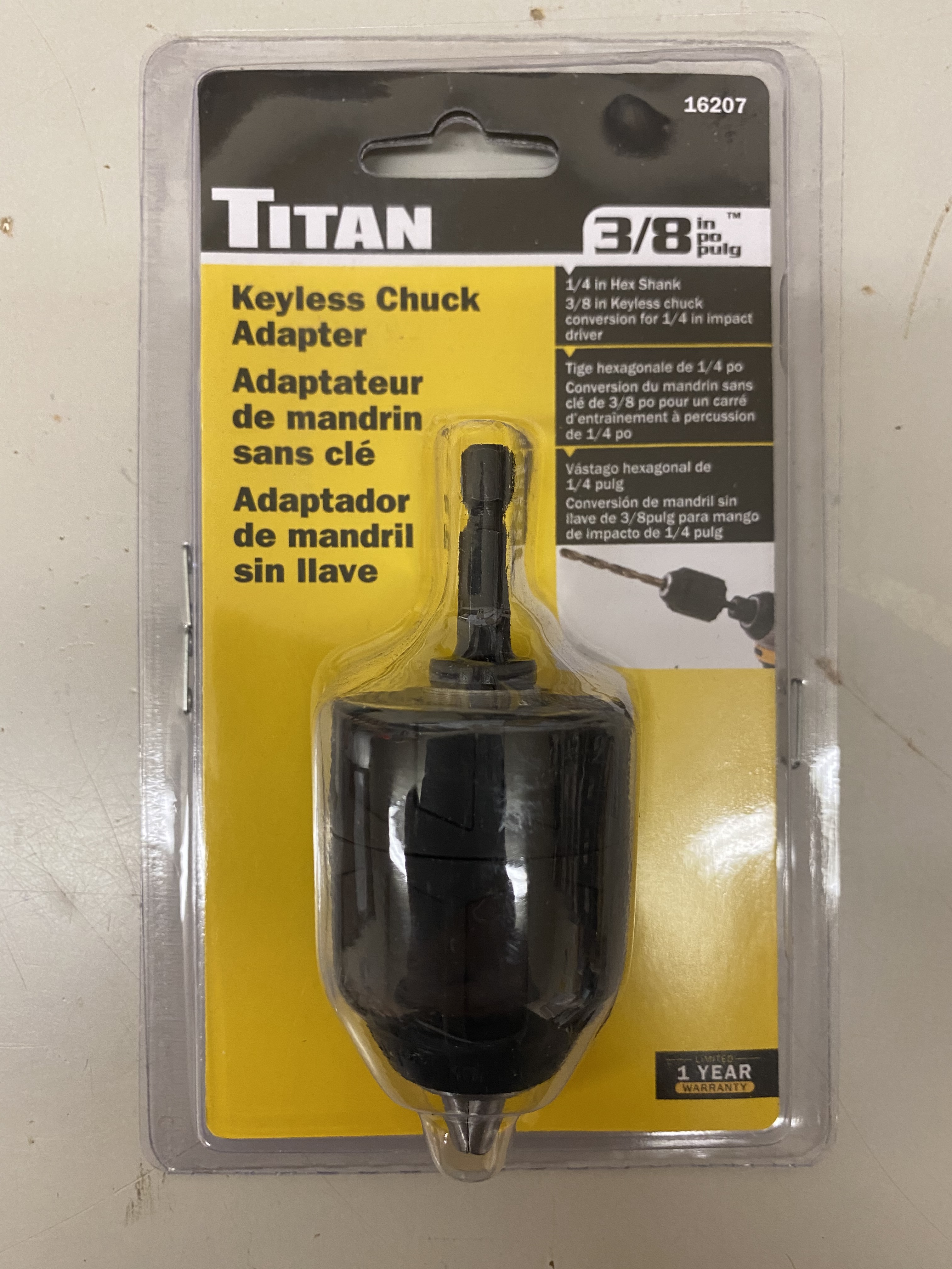


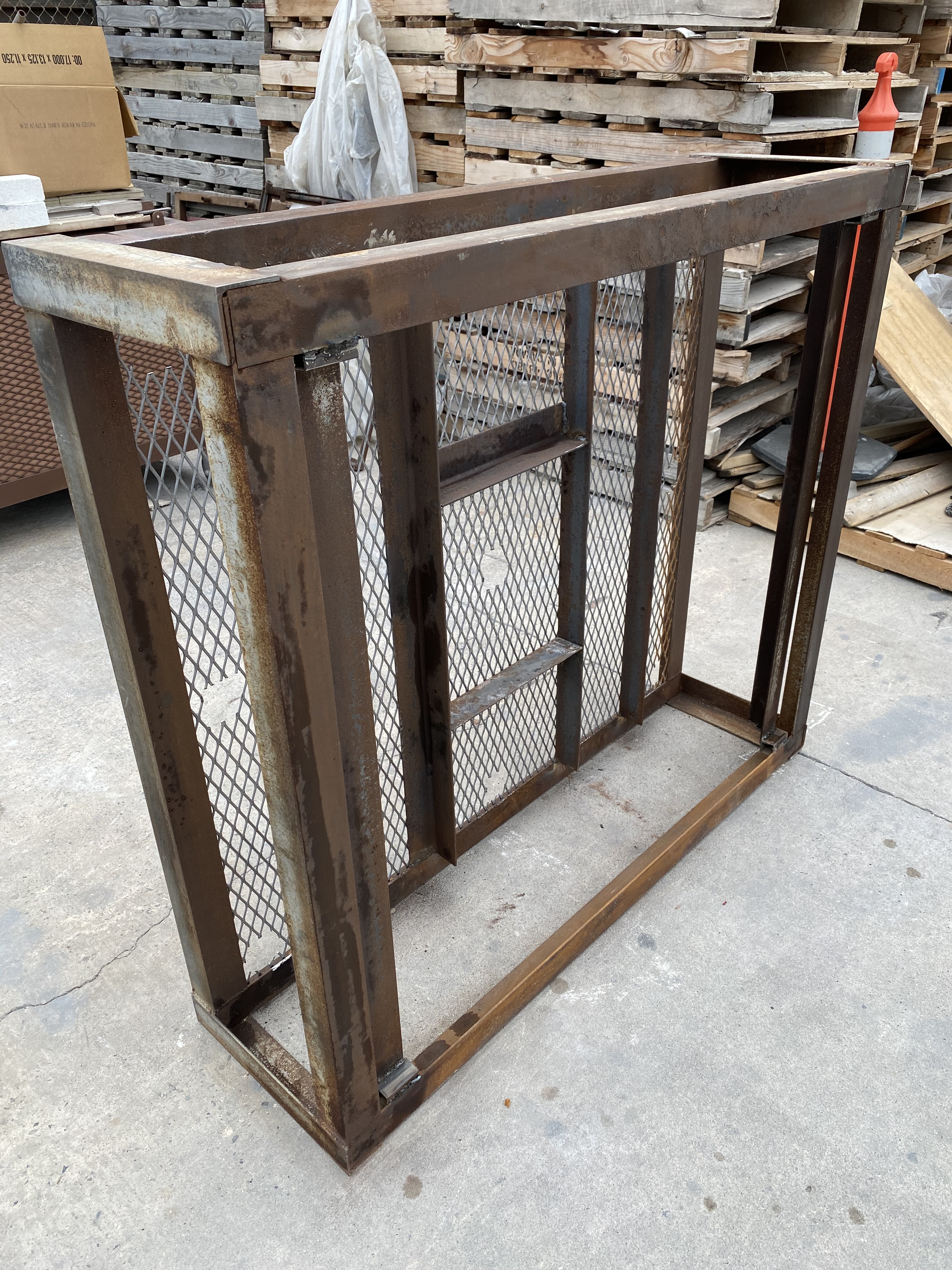
This Titan drill bit adapter allows you to use a vey small drill bit such as a #70 in a regular sized drill motor. It is also designed to be used with a battery powered impact wrench which is much easier to handle than a standard electric drill motor. The wall frames are constructed of #9-3/4 inch expanded metal, 1 inch angle iron, 1/2 inch square tubing and some flat bar to get the 48″ sheet of expanded metal to fit the dimensions of the kiln frame. Whatever works. But keep it light weight as much as possible because the panels are lowered by hand and could be overwhelming for someone to lower and raise. The middle pic shows the hinge assembly which is made up of a tube, a 1/2 inch bolt and a nut. I am visually lining it up with the kiln frame. 1/2 inch square stock of metal is to be welded to the head of the bolt.
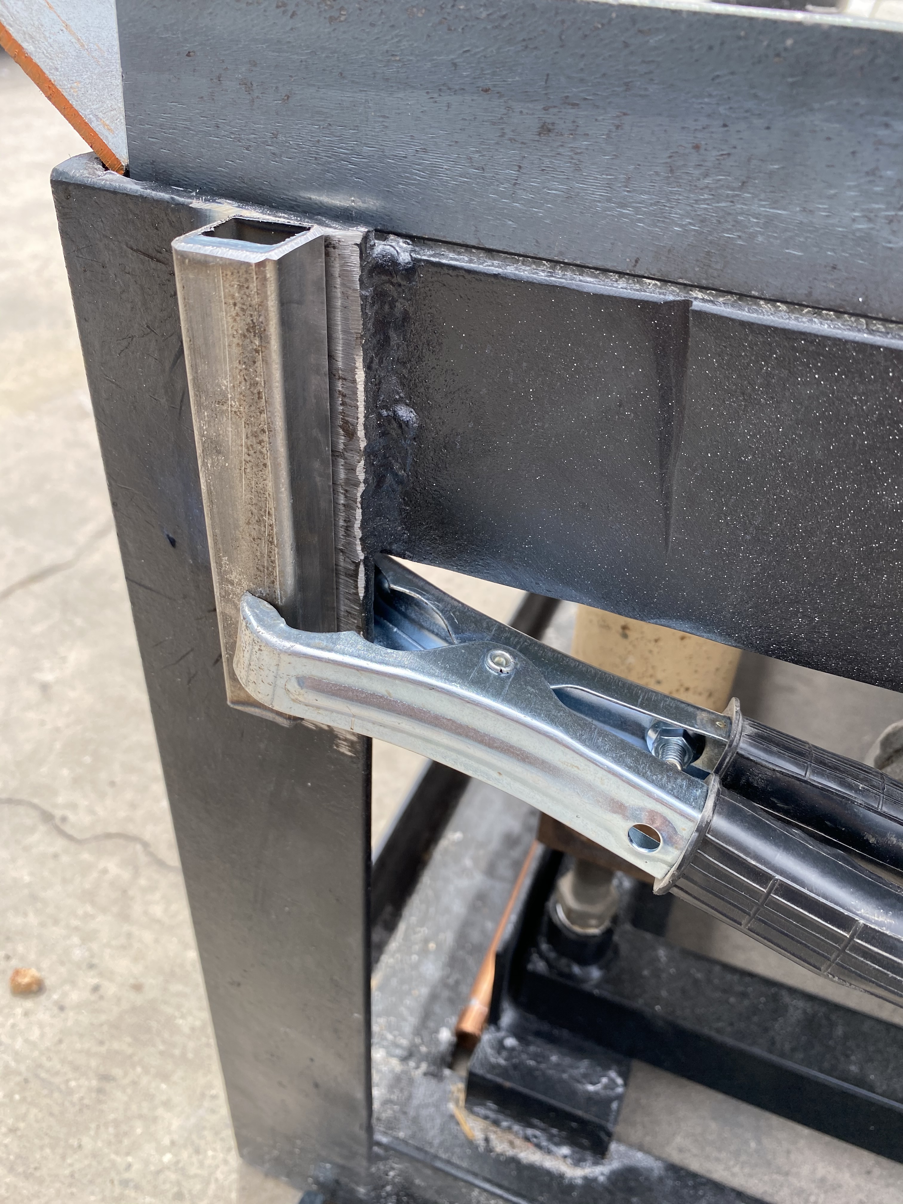


Square tubing is welded on the two sides at the corners and receive the square rod that is welded to the head of the 1/2 inch bolt. On lower left and right sides of the wall panel are round tubes that are welded in place and receive the 1/2 inch bolts. Align all the parts, spot weld to check for fit and proper movement and then apply the finish welds.Then a nut is screwed onto the bolt. Not shown is a small hole that is drilled through the square tube and square rod. 9 gauge nichrome or durable wire is fed through the hole and bent around the square tubing. This keeps the wall panel from lifting out of the square tubes.
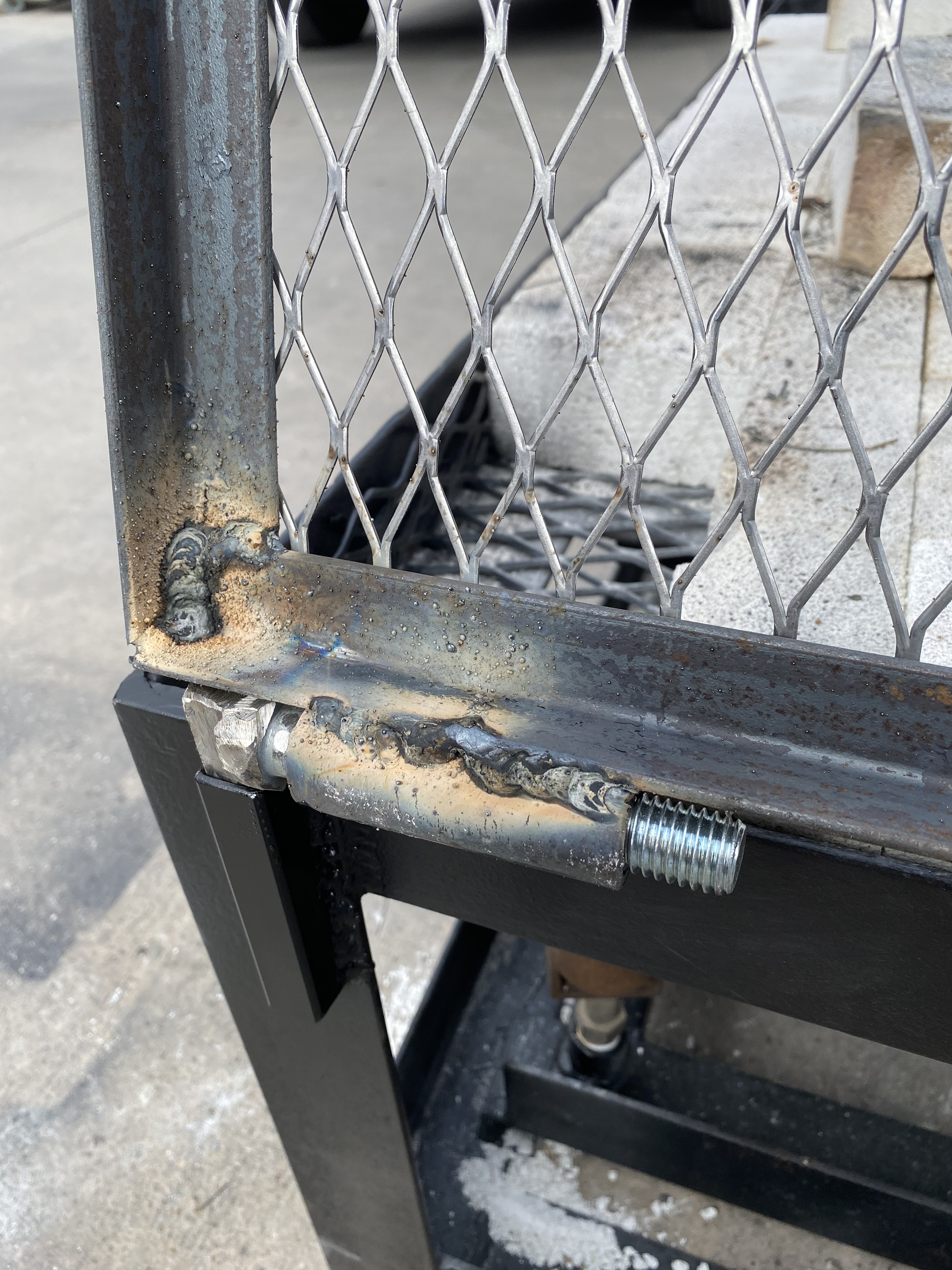


Hinge assembly.


Each wall panel has a “roof” that is part of the panel. Play with the dimensions, knowing that the edges running from the corners to the top where a flue will be, need to be of similar spacing as that of the corners of the side walls. Then spot weld the “roof” elements and test the fit of the framing at the top down to the base.

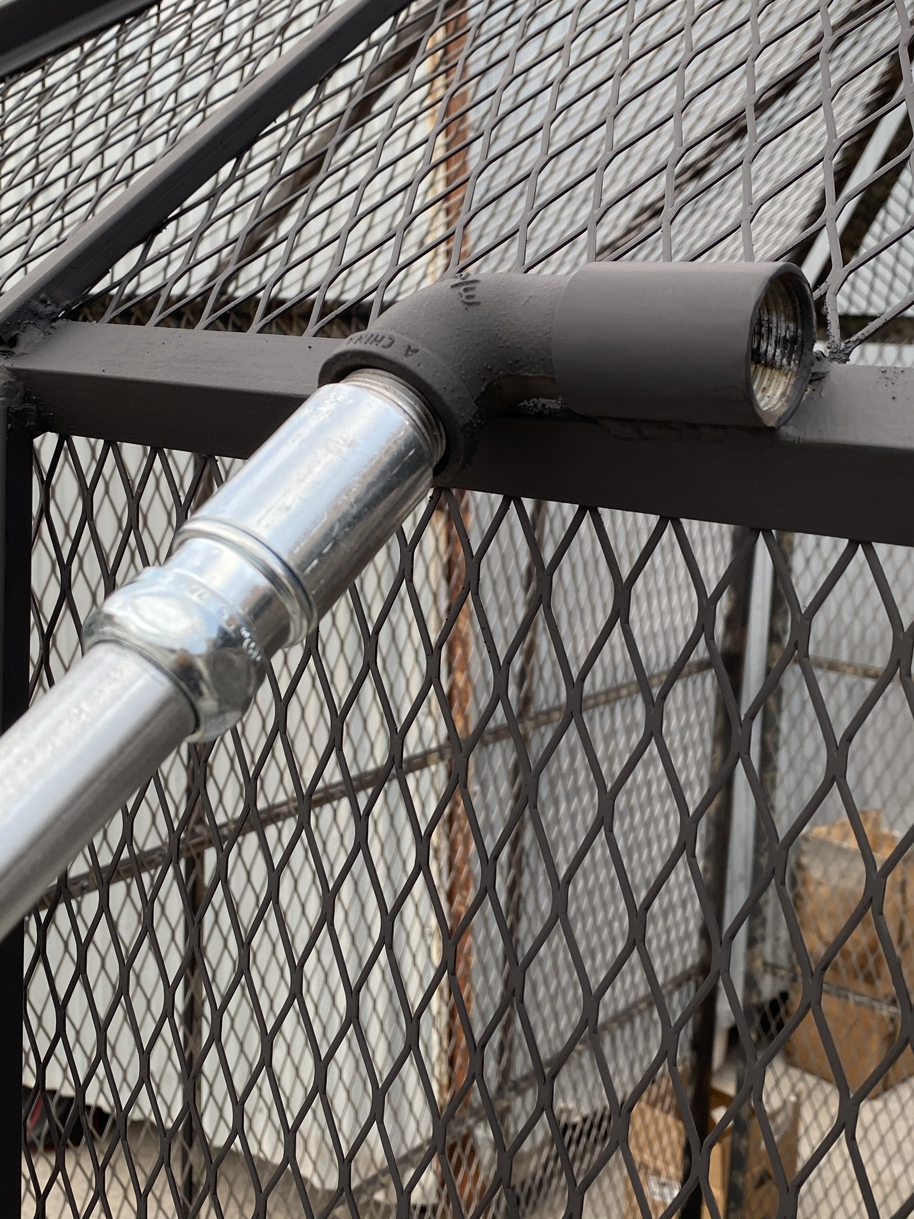

A 3/4 inch coupling, street elbow, nipple, another coupling and a twist fitting are attached to a 10 foot long , 3/4 inch conduit. Very strong and light weight. Be sure to spot weld all of the parts to the conduit so it does not come apart on the individual who is lowering a panel. The street elbow needs to be screwed in several turns into the coupling before the coupling is welded onto the panel frame. it makes an awesome hinge that allows a full range of motion when lowering the panel.
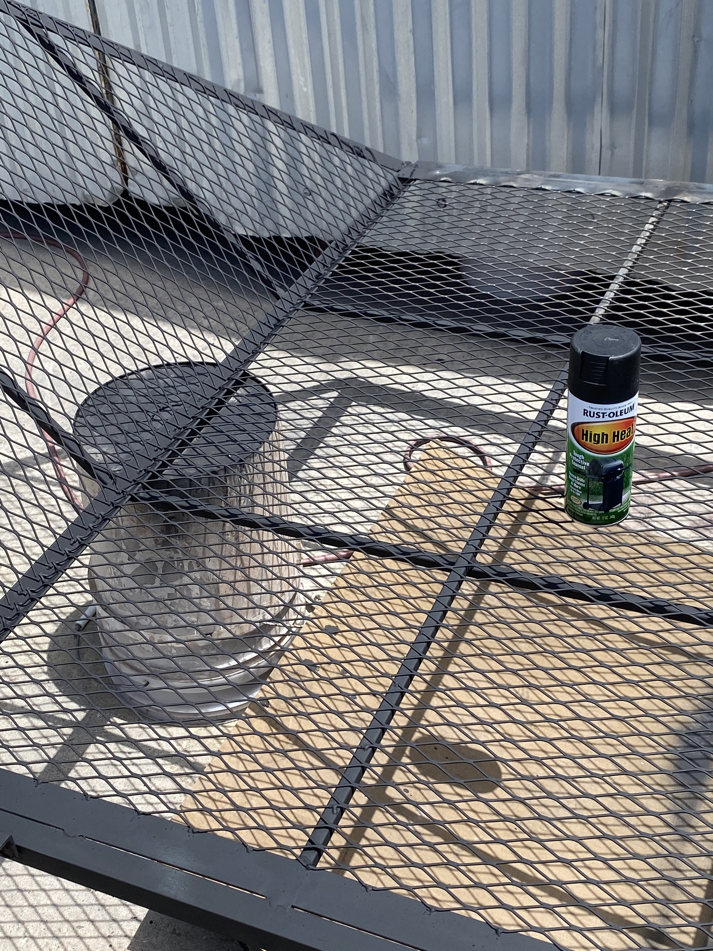


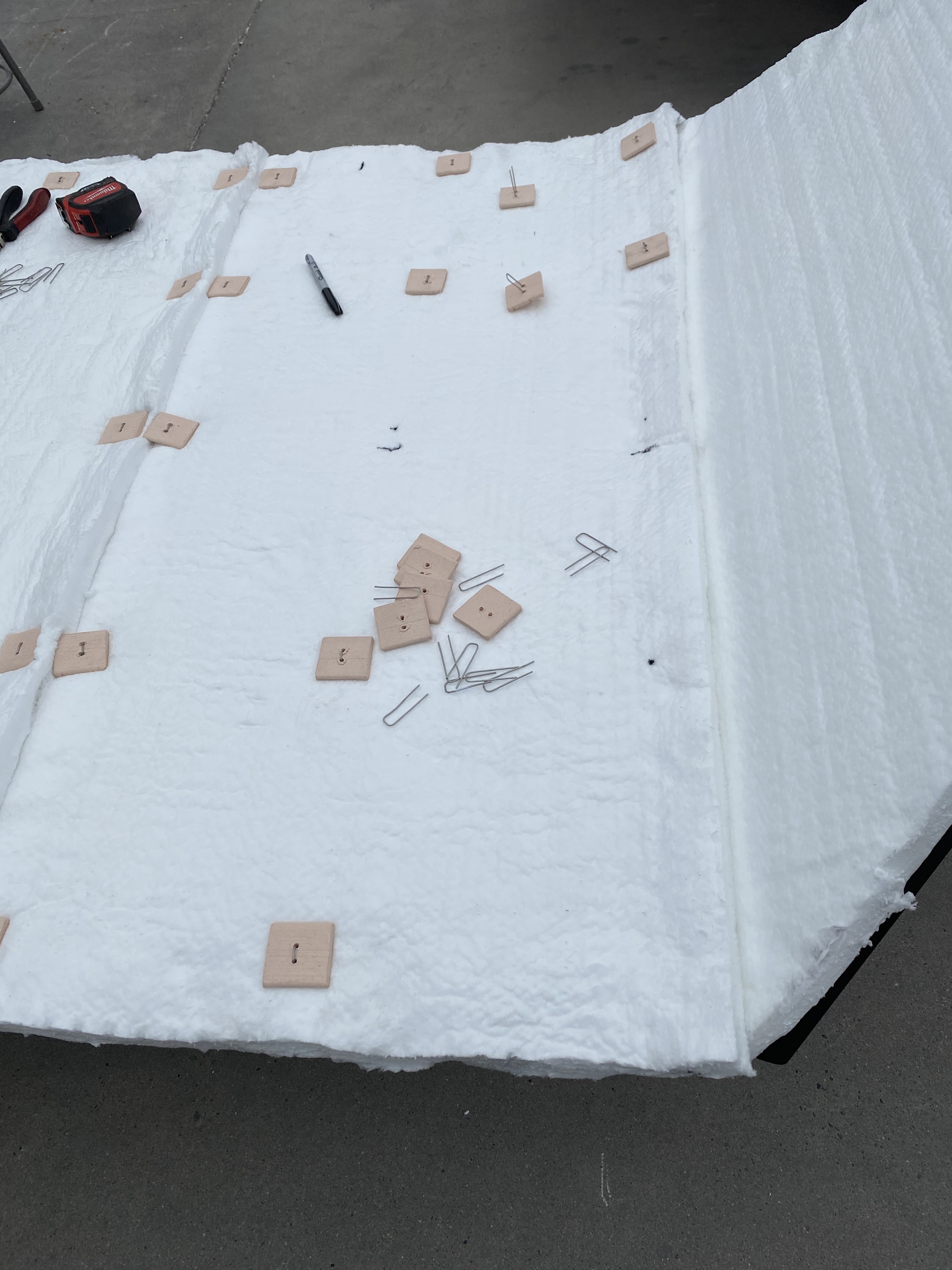
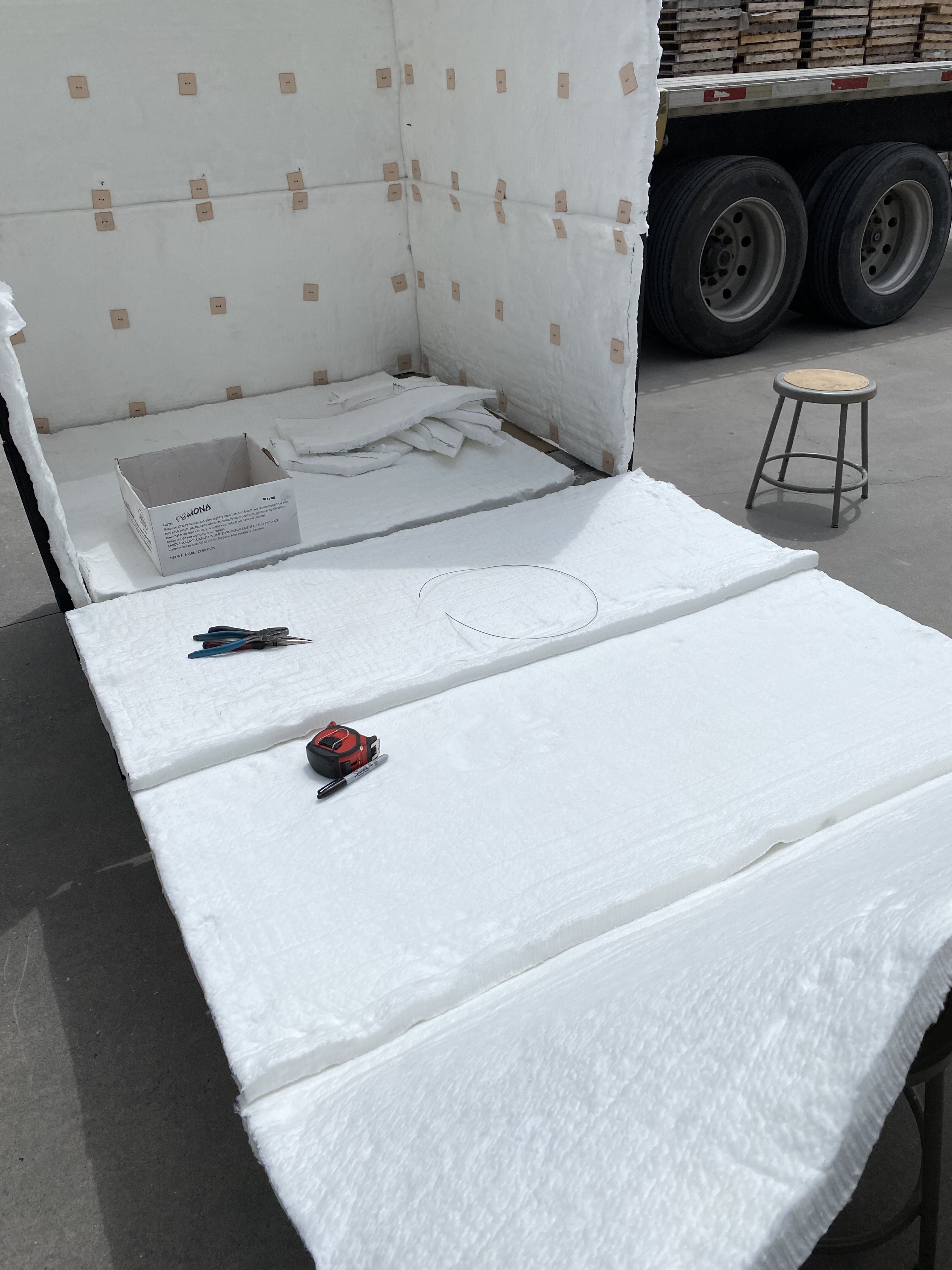
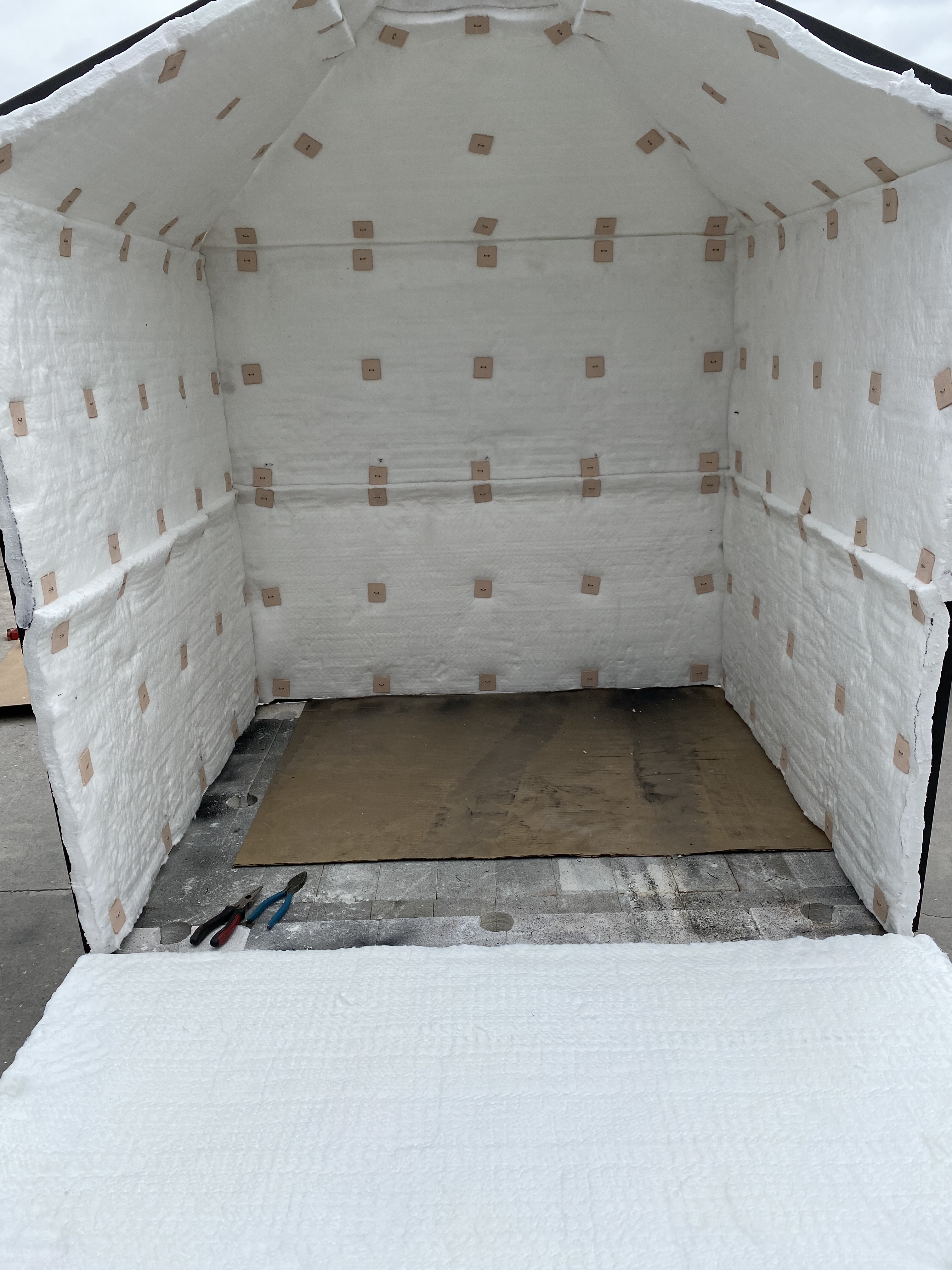
Spray metal with high temp paint. Start layout of the fiber. It will extent out an inch past the edge of the brick in order to have a good seal at the floor. Lower the panel to a height that is comfortable for attaching the ceramic buttons with 15 gauge nichrome wire. You will be on the ground and on your back to make some of the attachments.

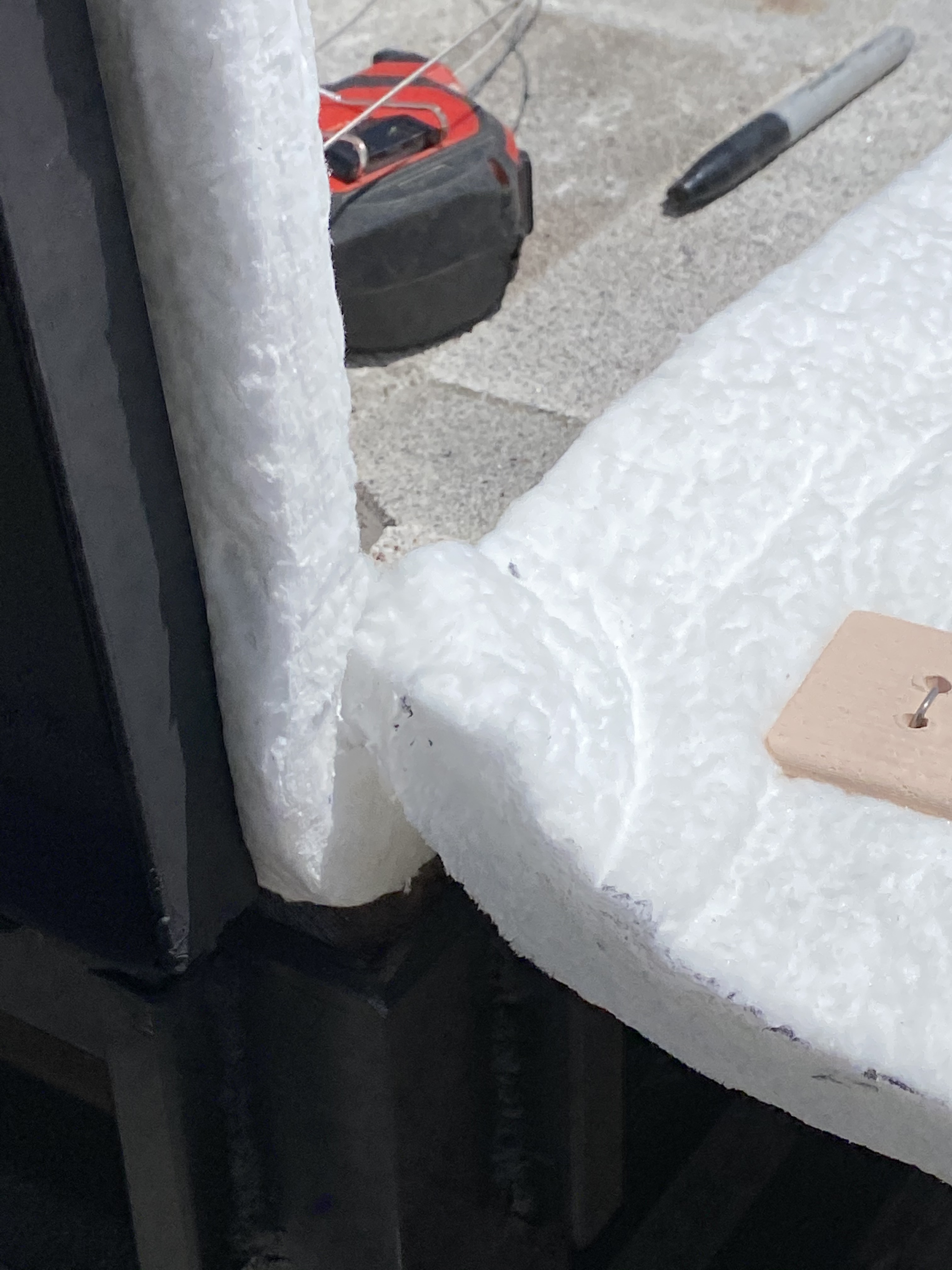

Inspect the fiber placement to be sure there is a good seal at the bricks. Set only enough buttons to hold the fiber in place until you are sure the fiber is lined up well on the metal frame.
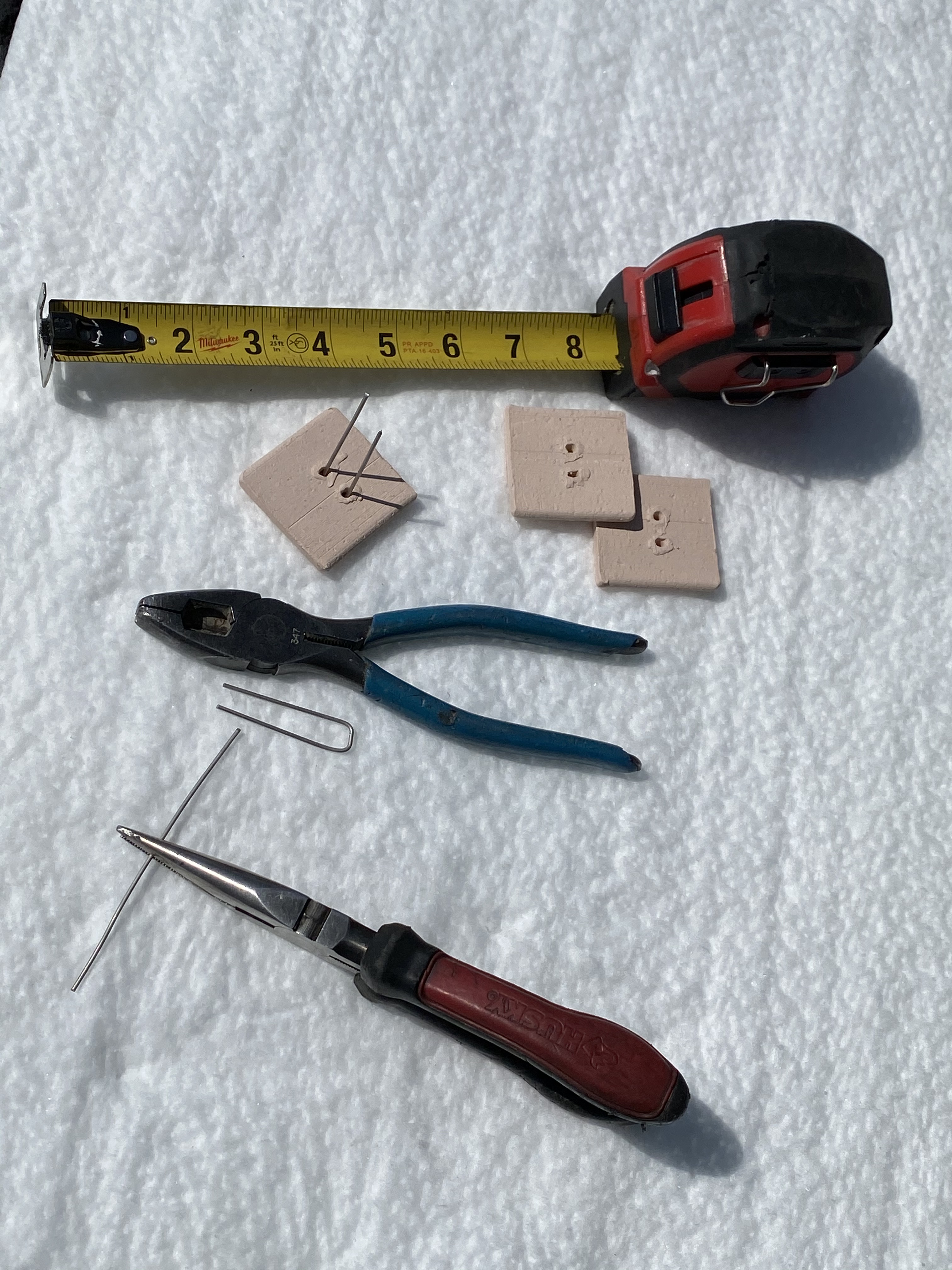


Tools of the trade…


Measure the length of the U-shaped wires and then bang out a bunch of them before getting started.

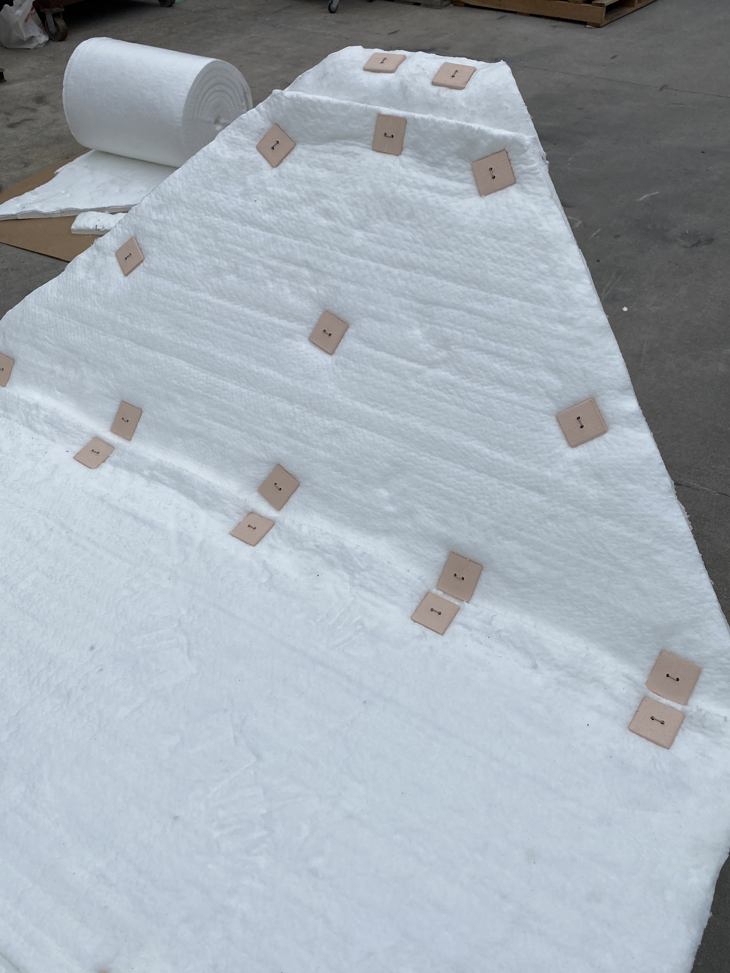
Overlap, trim and place buttons next to and over the overlap sections. Count the number of buttons you will need before starting on this.
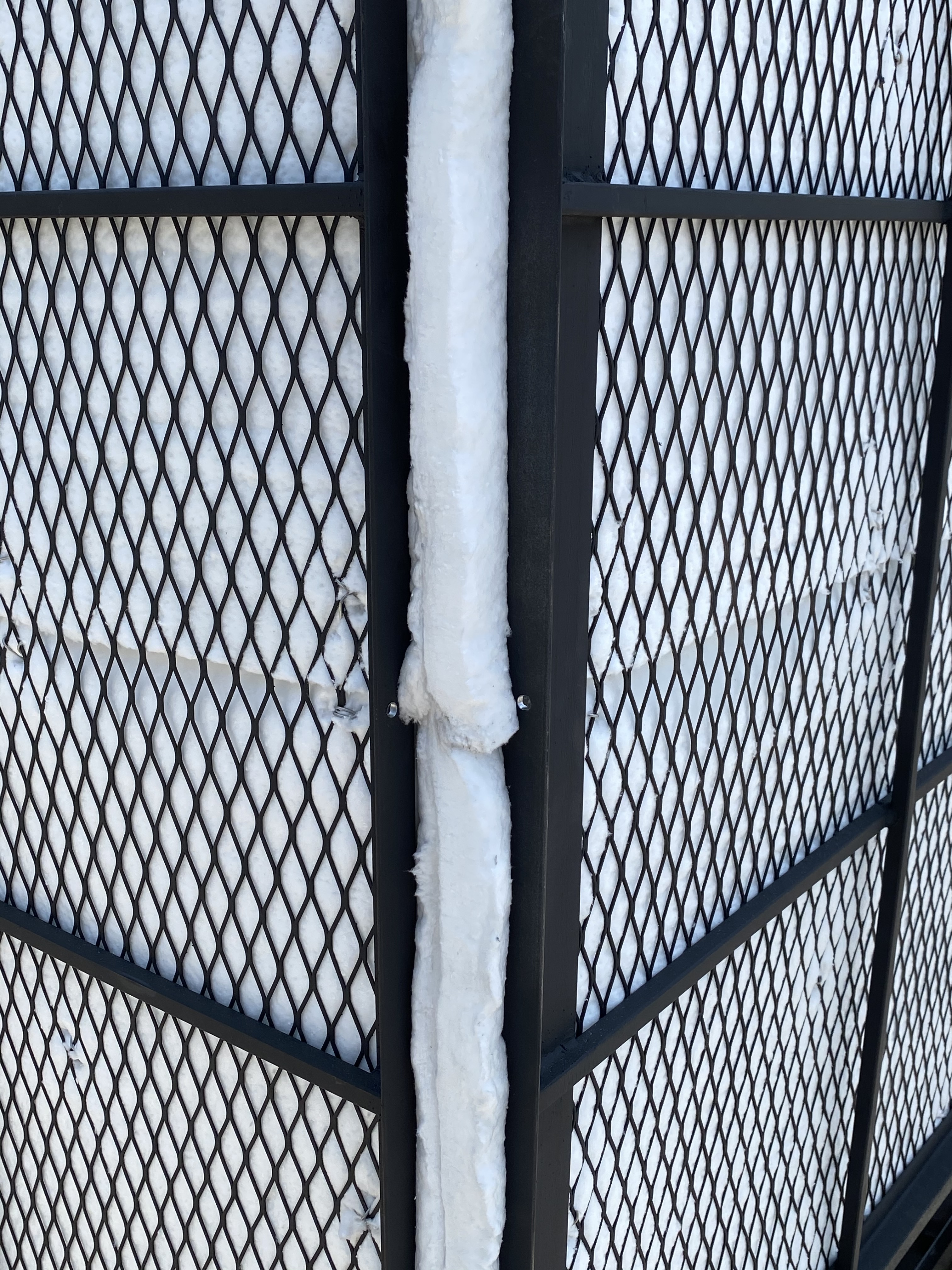

Pull the panels together to see how the fit is. If it is not adequate, you can always add a slice of fiber in any gaps. Drill holes in the frame edges so nichrome wire can be inserted to hold the panels together during the firing or storage.
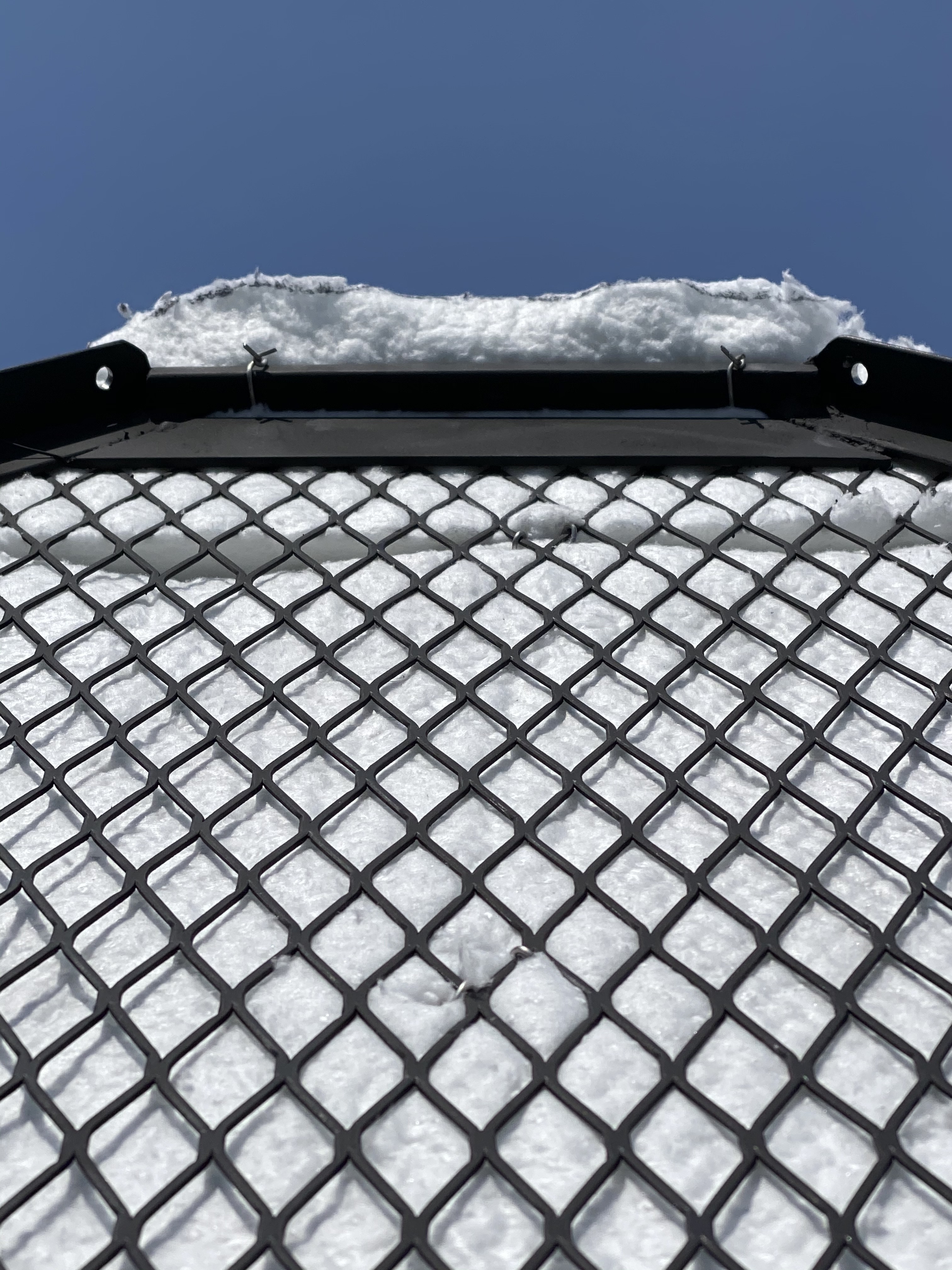

Be sure the fiber extends beyond the top of the flue area so heat does not distort the metal frame. A piece of loose fitting fiber can be placed on top during the first test firing at night to view the air/fuel ratio of the atmosphere as indicated by flame or no flame coming from the flue at 1800F. This can be used to lessen the size of the opening or as a damper.


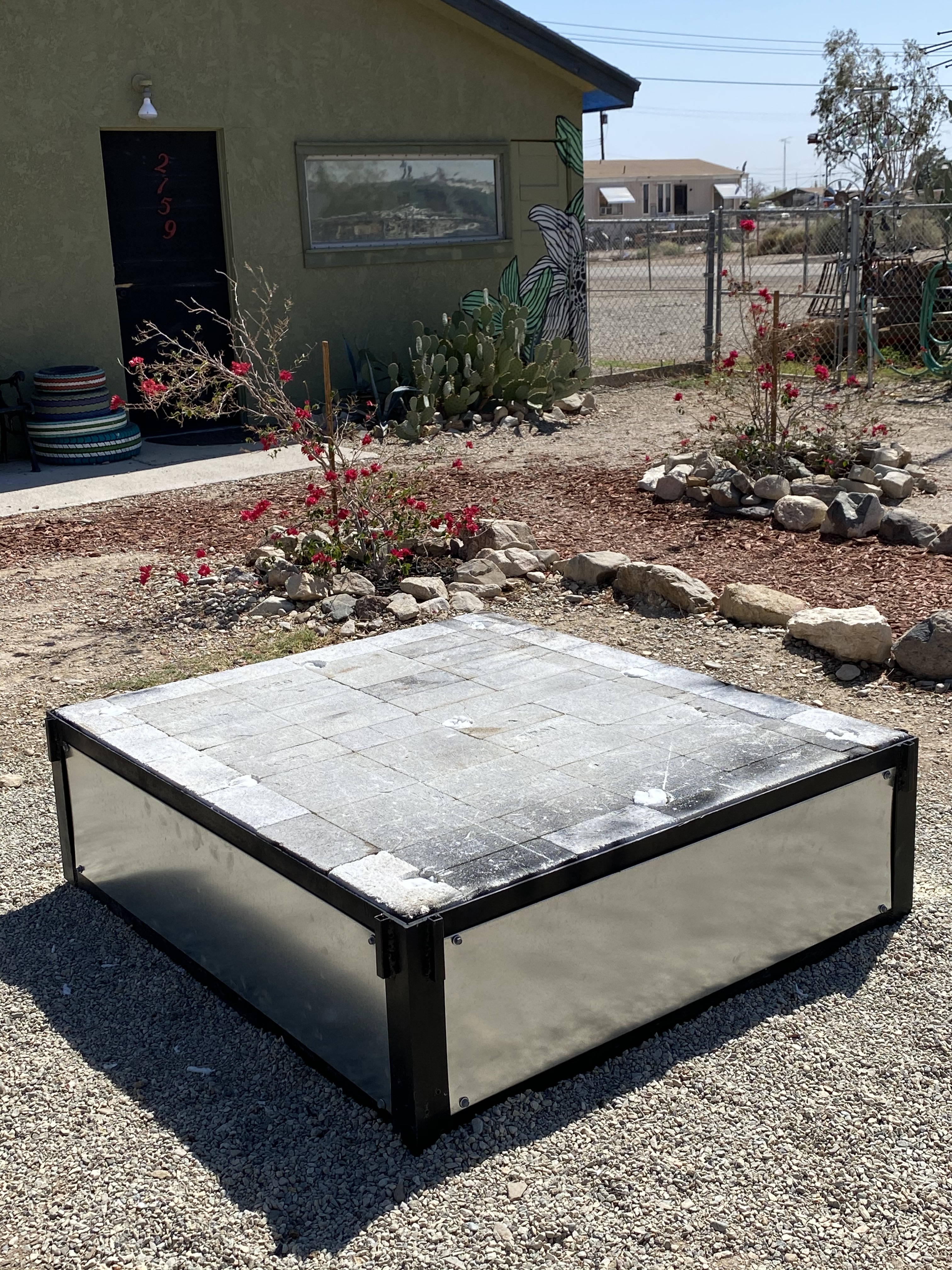
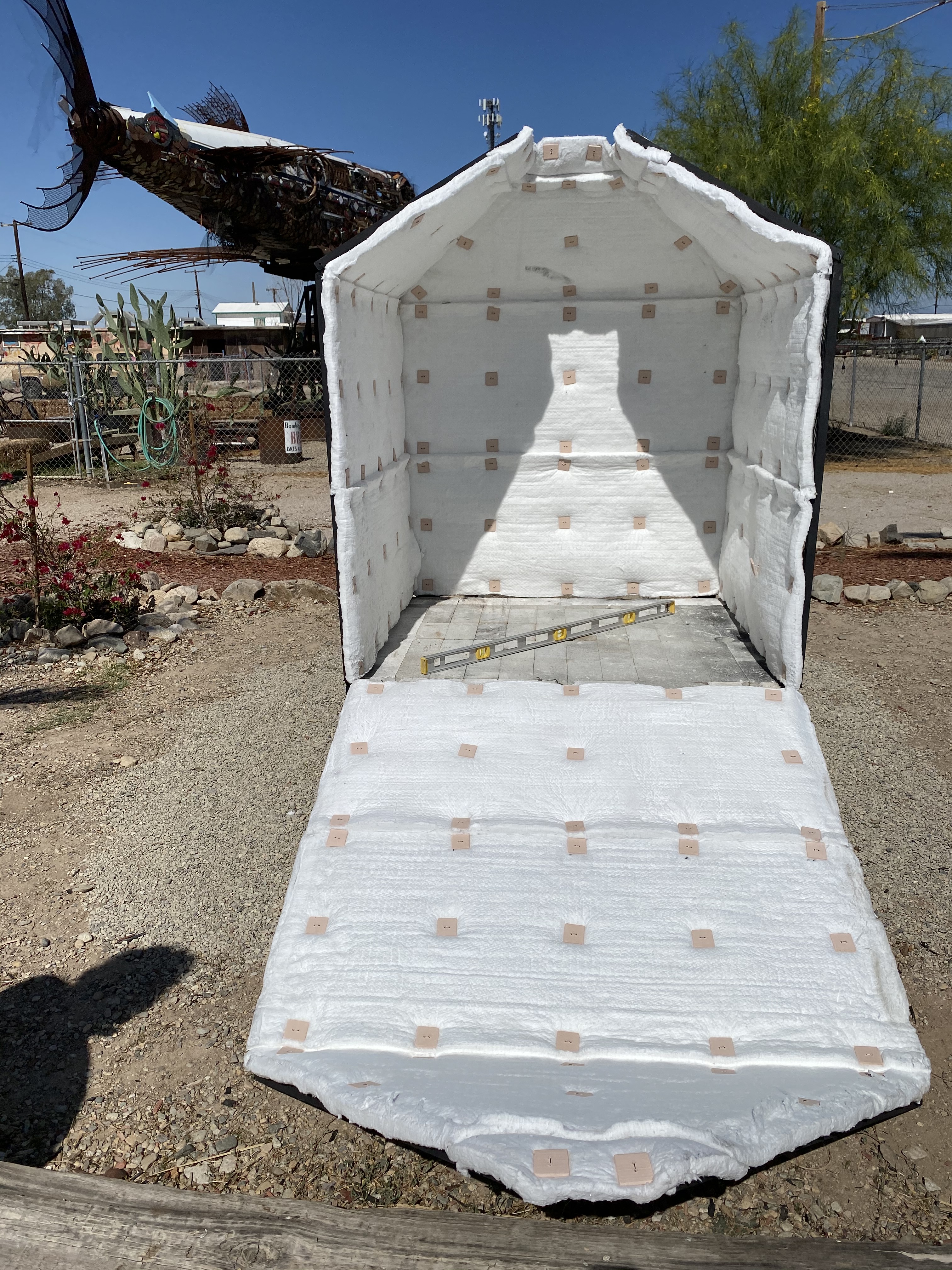
The panels can be removed and stored or left exposed to the elements. Just be aware that birds and rats love to use fiber blanket for nesting. Galvanized sheet metal has been added to cover up the hardware and makes for a pedestal for the fired sculpture.


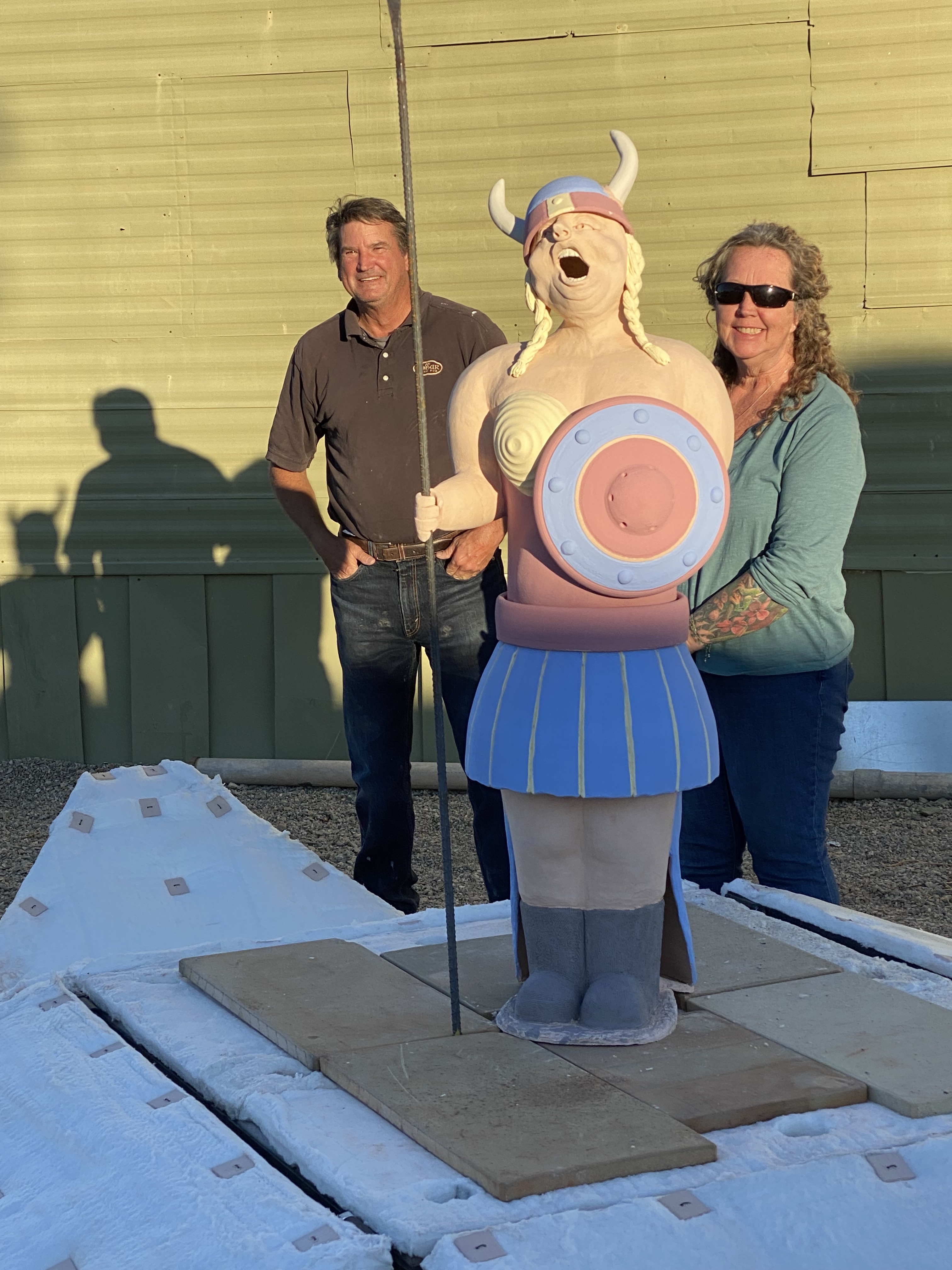
Testing out the system. Firing the kiln to 1800F with blower in foreground. Matt Evans and Barbara Hass, creators of the “Opera Singer”.

 copy")


")
")


